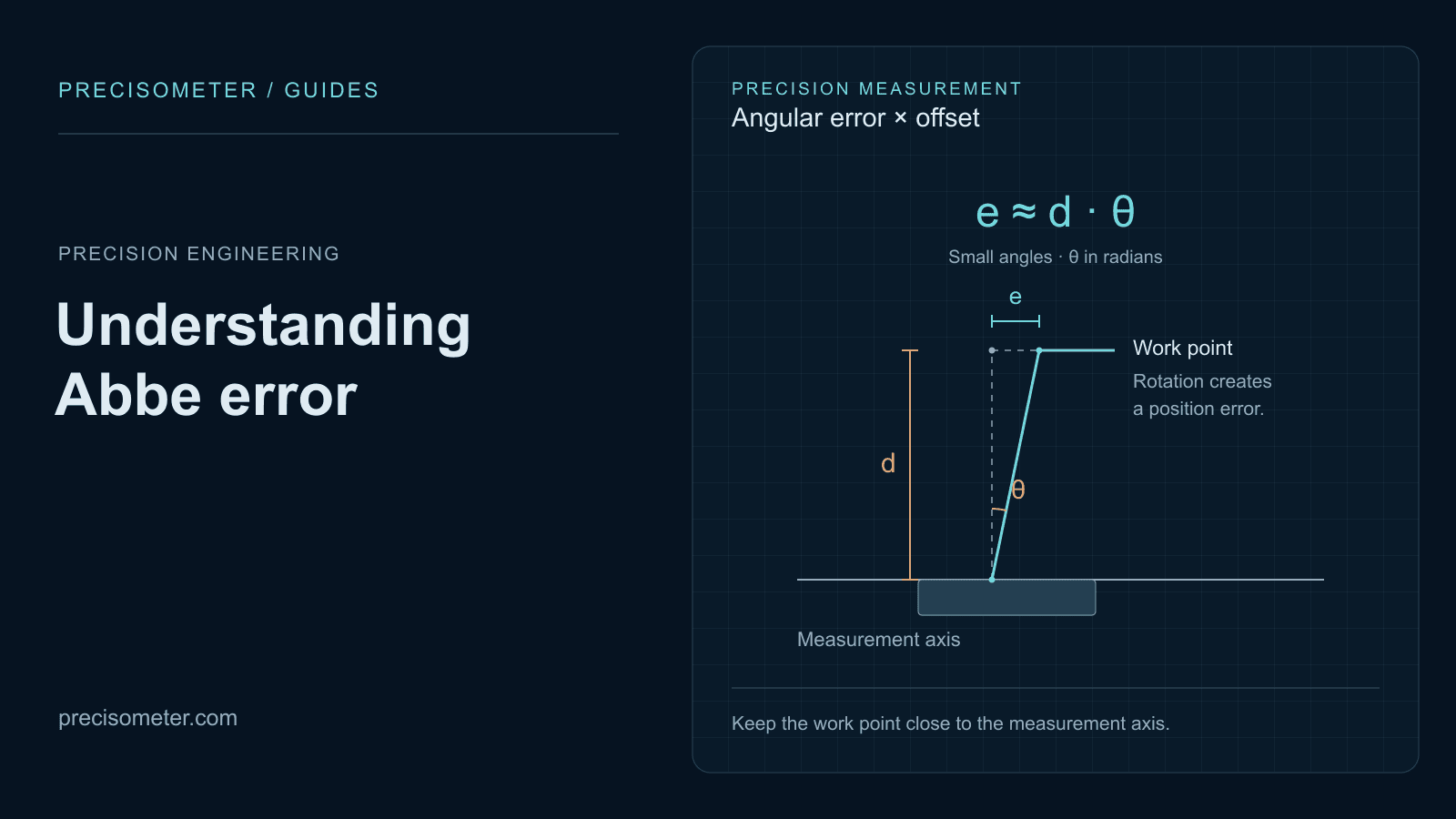
Abbe error: what it is and how to calculate it
Angular error multiplied by offset — the largest geometric error in most precision machines, first order rather than second, and absent from every datasheet because half the product belongs to you.
Technische Kennis
Praktische selectiegidsen, specificaties van echte producten en interactieve tools voor onderzoekers die optische, imaging- en precisie-positioneringssystemen bouwen.
Start vanuit het experiment, niet vanuit een generieke productlijst.
Verbind specificaties direct met de tradeoffs die er daadwerkelijk toe doen.
Pas parameters aan en zie direct hoe het advies reageert.
Praktische gidsen geschreven door onze optisch ingenieurs en systeem-engineers.

Angular error multiplied by offset — the largest geometric error in most precision machines, first order rather than second, and absent from every datasheet because half the product belongs to you.

Why load capacity is really a moment specification, why Abbe error usually beats the quoted accuracy, why a rotary encoder on the motor is not position feedback, and when top speed is unreachable by geometry.

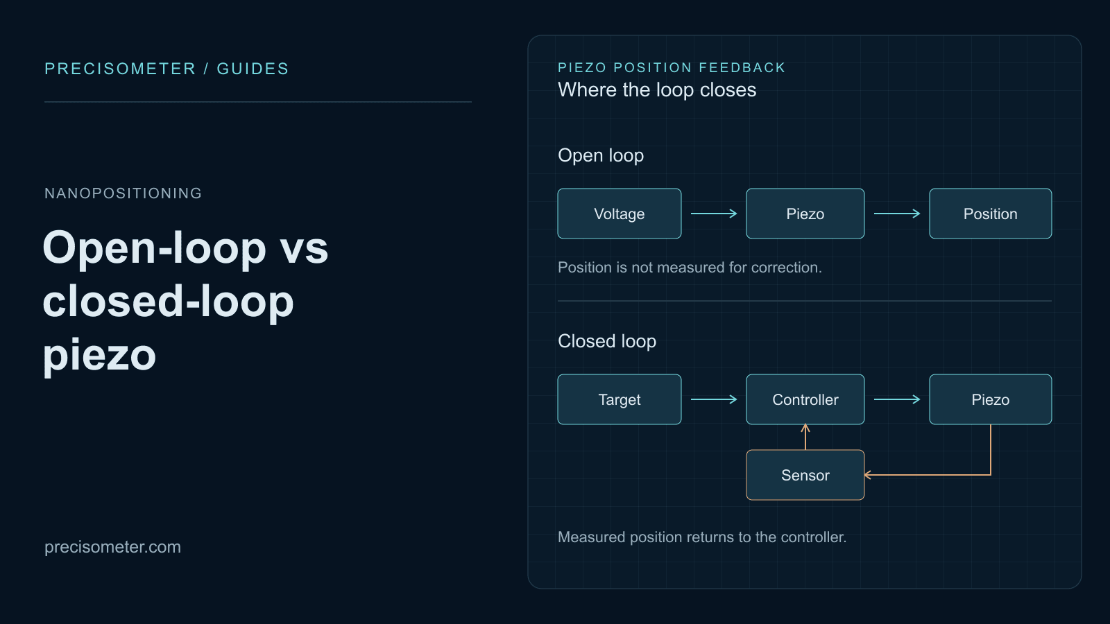
Why an open-loop piezo is wrong by 15 % of its travel, how creep grows with the logarithm of hold time, what strain-gauge and capacitive feedback actually fix — and the bandwidth and sensor noise a servo costs you in return.

Turn fibre-to-chip coupling tolerance, polarization, device Q, and port count into a complete source, detection, coarse-alignment, and closed-loop nanopositioning stack.

Translate fluorophore bands, Stokes shift, and sample state into a defensible excitation source, optical filters, collection geometry, monochromator, and detector architecture.

Which wavelength actually couples into plant tissue, the energy dose each growth stage needs, why targeting overhead rather than watts limits hectares per hour, and the Class 4 hazard case that shapes a field machine.

How much power each imaging modality actually needs at the sample, which excitation lines match your fluorophore panel, why modulation bandwidth beats raw milliwatts, and the photon count above which laser noise finally reaches the image.

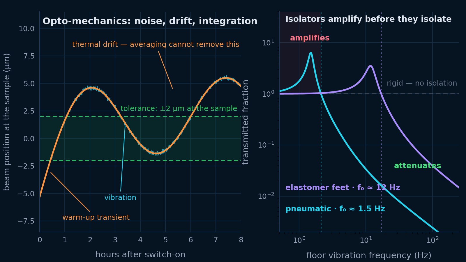
Vibration, thermal drift and mechanical integration are one problem. Budget the motion at the sample, then specify the table, the isolation, the mounts and the beam height that budget asks for.

Isolation only starts above √2 times the isolator natural frequency — below it a heavy table on stiff legs amplifies the floor. Where that corner sits is the specification; mass is not.

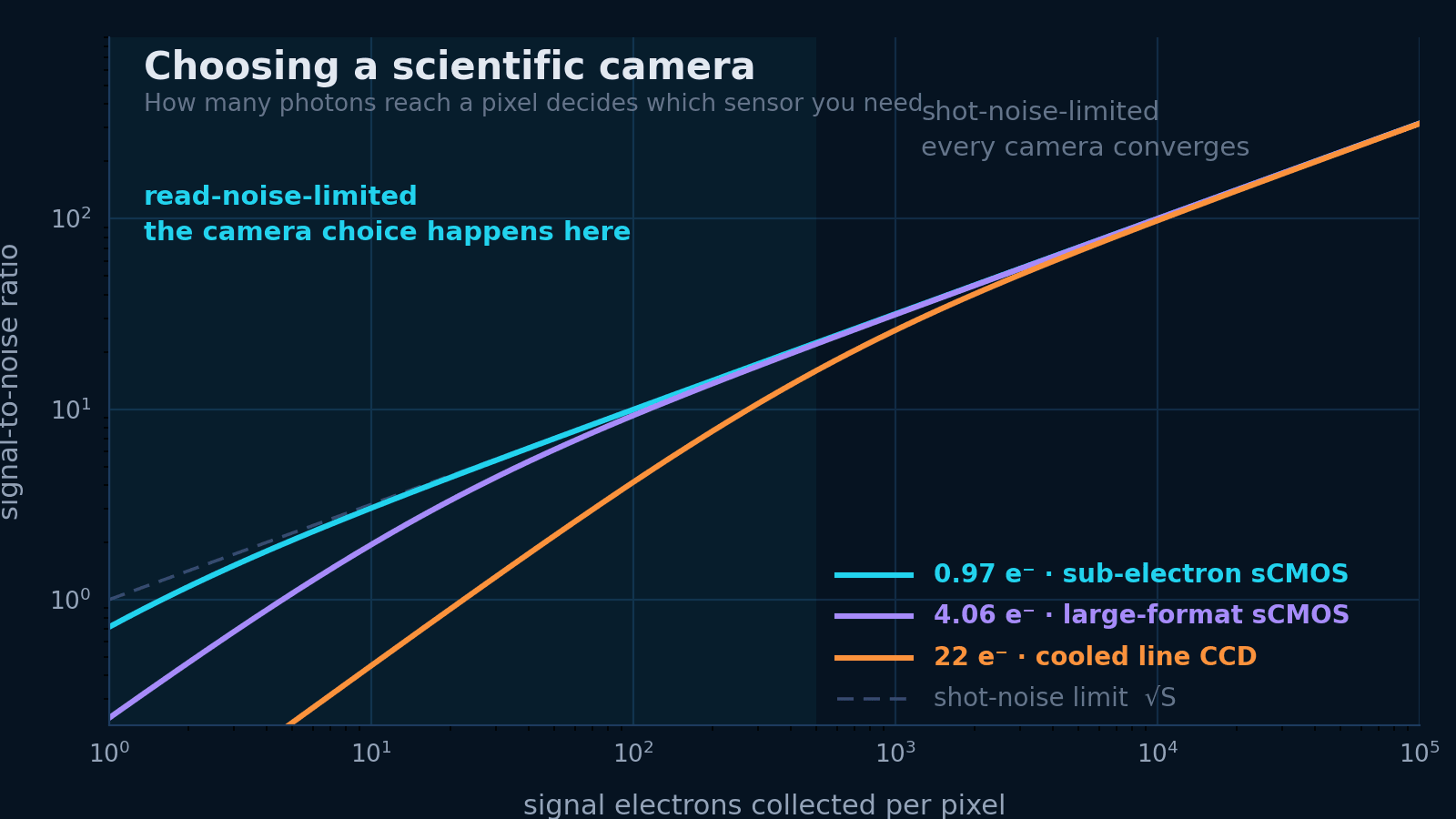
Which sensor technology your photon budget actually needs, why rolling and global shutter answer different questions, and how to check the data can leave the camera at all.

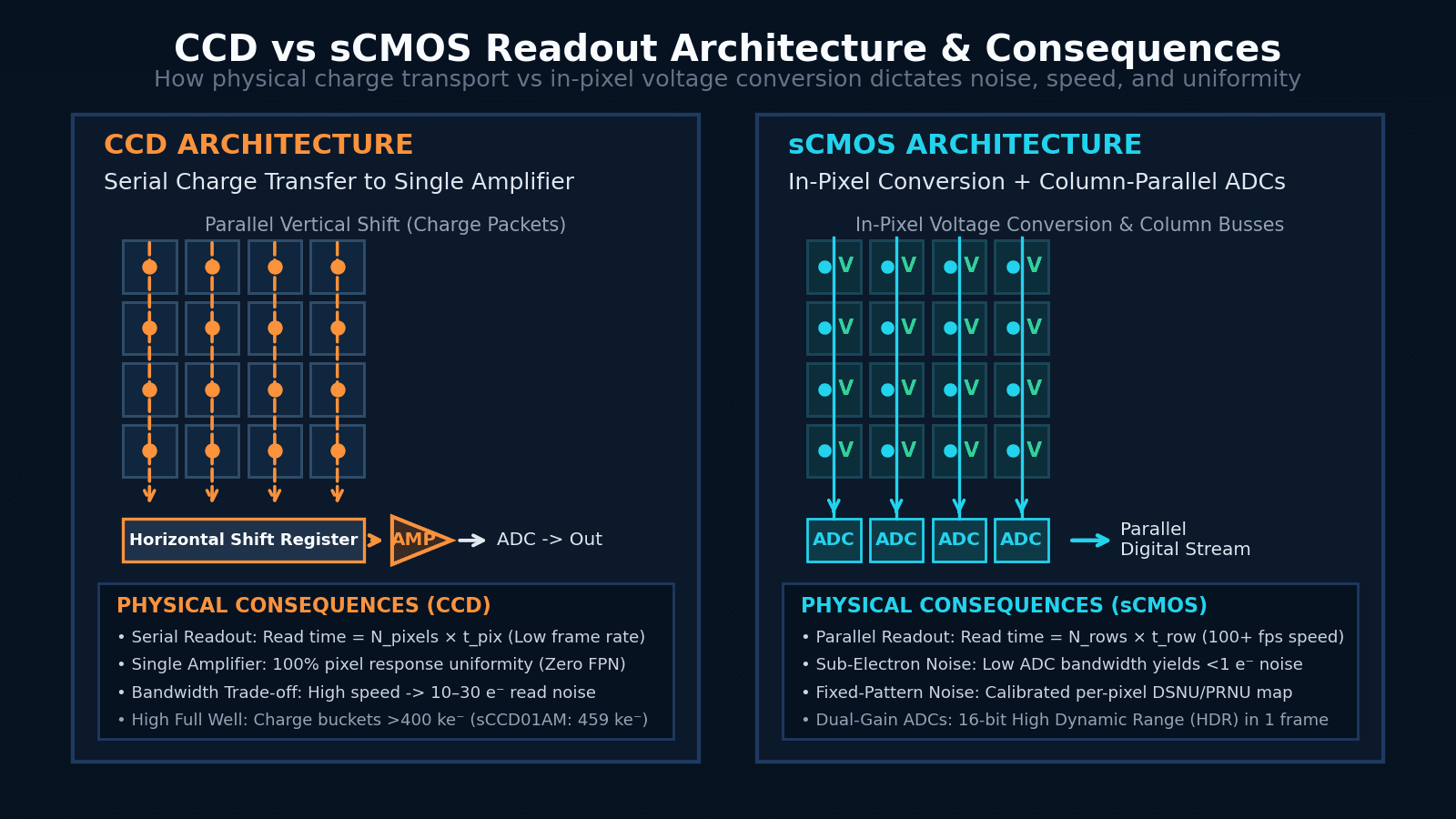
How physical charge transport versus in-pixel voltage conversion dictates readout speed, read noise, blooming, fill factor, and fixed-pattern noise in scientific detectors.

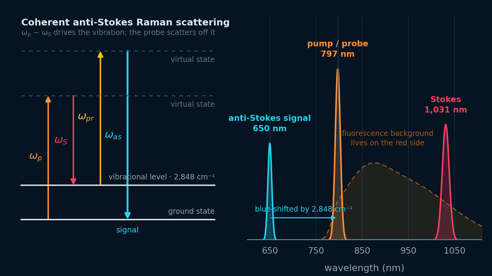
Coherent anti-Stokes Raman scattering, from the four-wave-mixing physics to the hardware: excitation schemes, pulse width versus linewidth, the delay line that carries the spectral axis, and the detection chain.

Signal scales as P²/(τ·f), so the pulse your objective stretches from 100 fs to 300 fs costs two thirds of your fluorescence at identical average power. The beam path, part by part, and an interactive excitation budget.

A thinner sheet is always a shorter sheet — waist goes as 1/NA but the field it stays thin across goes as 1/NA². SPIM, DSLM and mesoSPIM are three points on that one curve.

Design the pump, probe, delay line, monochromator, visible or SWIR camera, synchronization, and transient-signal budget as one experiment.

Connect fluorophores, pinhole size, Airy units, spatial sampling, scan timing, modulation, and power after the fiber in one practical design workflow.

Connect optical absorption to wavelength, pulse fluence, stress confinement, acoustic bandwidth, repetition rate, and synchronization at the sample.

Why wavelength is decided by photodamage, focal heating, and detector bandwidth rather than trapping force — and what laser noise costs you in piconewtons.

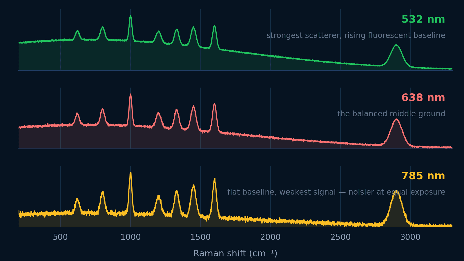
Balance the ν⁴ signal law, fluorescence background, silicon detector cutoff, and spatial resolution across 532, 638, and 785 nm.

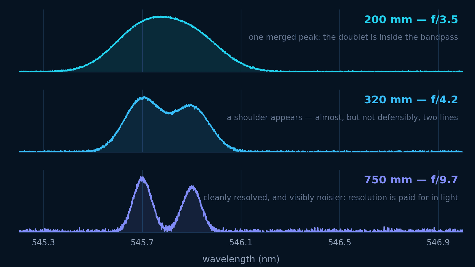
Focal length, grating, and slit are one decision: how finely to spread the spectrum and how much light to pay for it. Watch a doublet merge and split through real Omni-λ dispersion numbers.

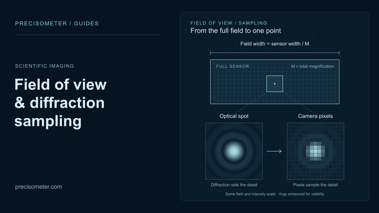
Calculate object-space pixel size, field of view, Rayleigh resolution, and sampling using real MAX and sMAX sensor formats.
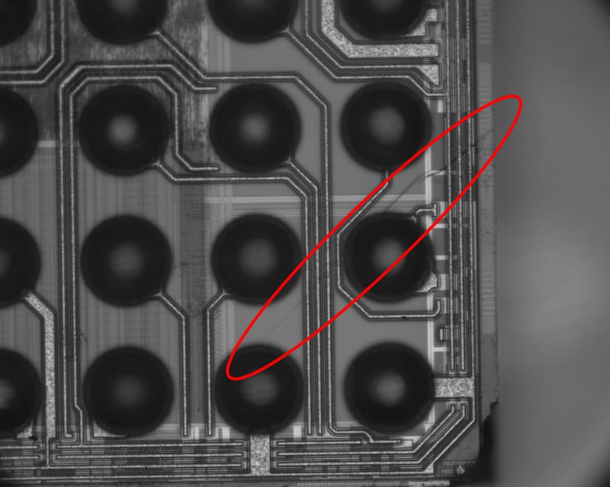
Design a through-silicon inspection setup for wafers and ICs: choose transmission, reflection, or emission imaging; then match wavelength, NA, sampling, and camera.

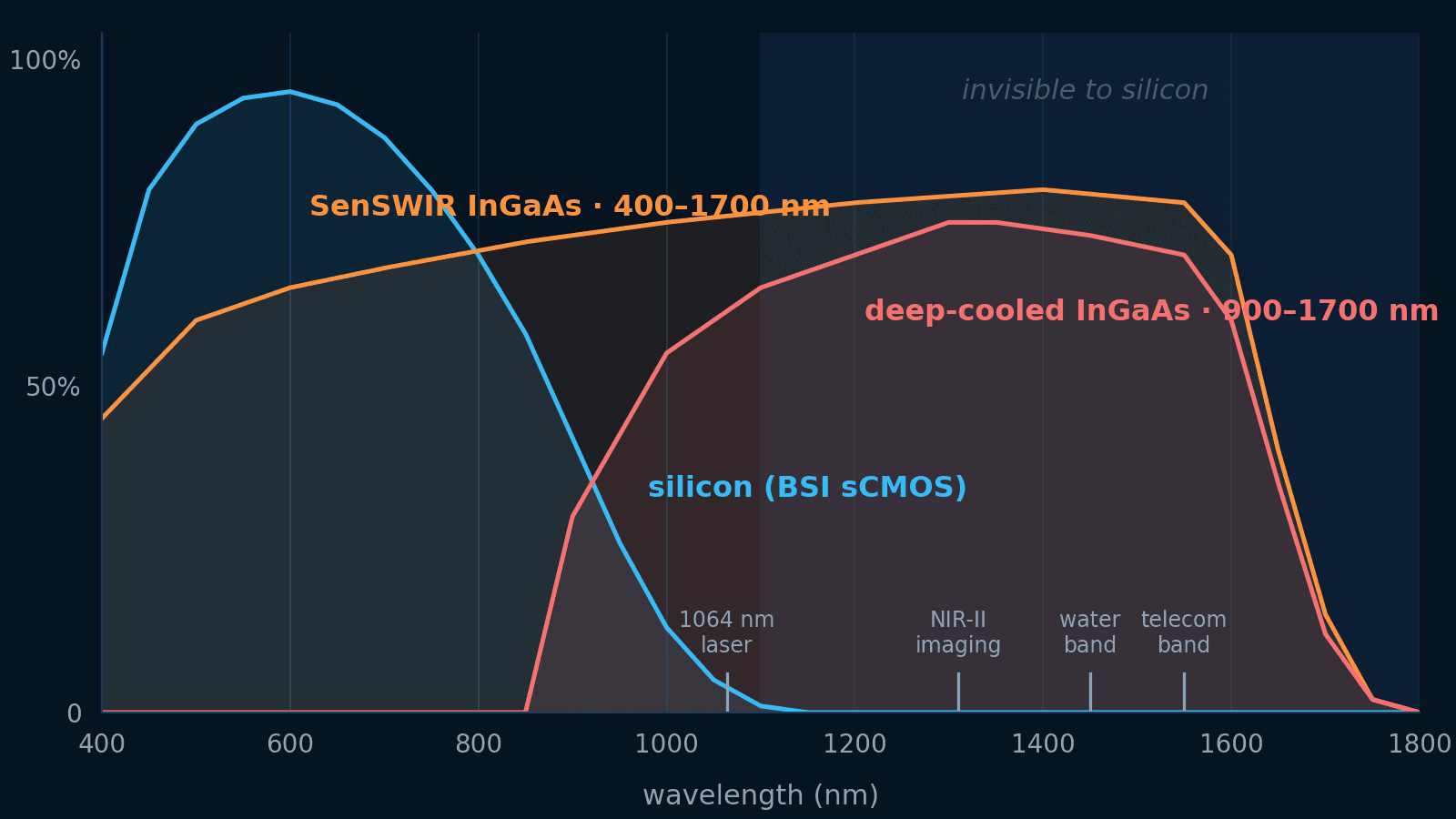
Silicon cameras go blind at 1100 nm. Compare InGaAs sensor families, dark current, and cooling with an interactive QE and SNR lab — and find which regime your measurement is in.

Understand quantum efficiency, read noise, pixel size, SNR, and optical sampling using real MAX and sMAX specifications.

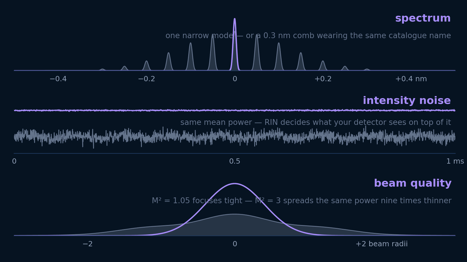
Linewidth, spectral width, RIN, M², and coherence length answer five different questions. Translate each into the units your experiment is designed in — and learn which ones not to pay for.

Single-mode fiber does not preserve polarization. Pin the state, erase it with a scrambler, or maintain it in PM fiber — which one your measurement needs, and the response time and extinction ratio that decide it.

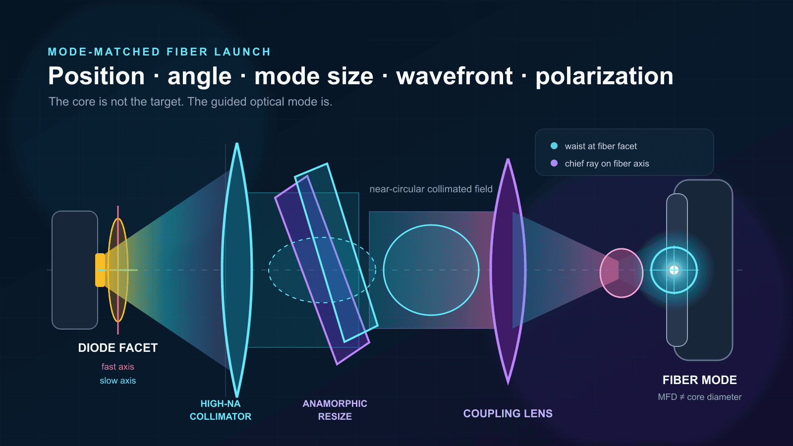
Take an asymmetric diode beam from collimation through mode matching, SM/MM/PM fiber selection, alignment, polarization, feedback control, and long-term stability.

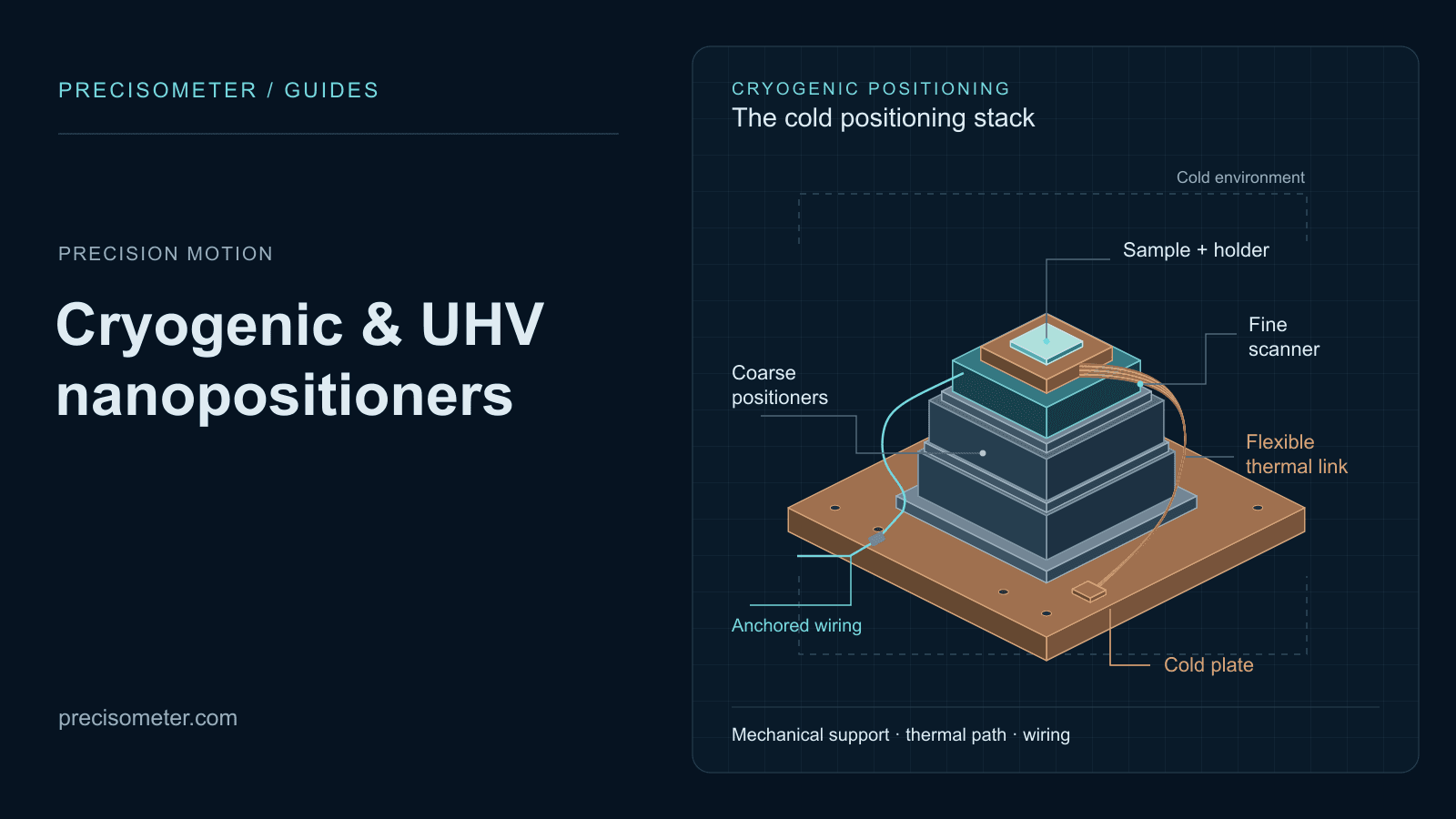
Translate temperature, pressure, travel, payload, feedback, and motion requirements into a defensible cryogenic-stage shortlist.

Design the trapping beam, objective, mechanics, imaging, QPD detection, calibration, and safety workflow as one instrument.

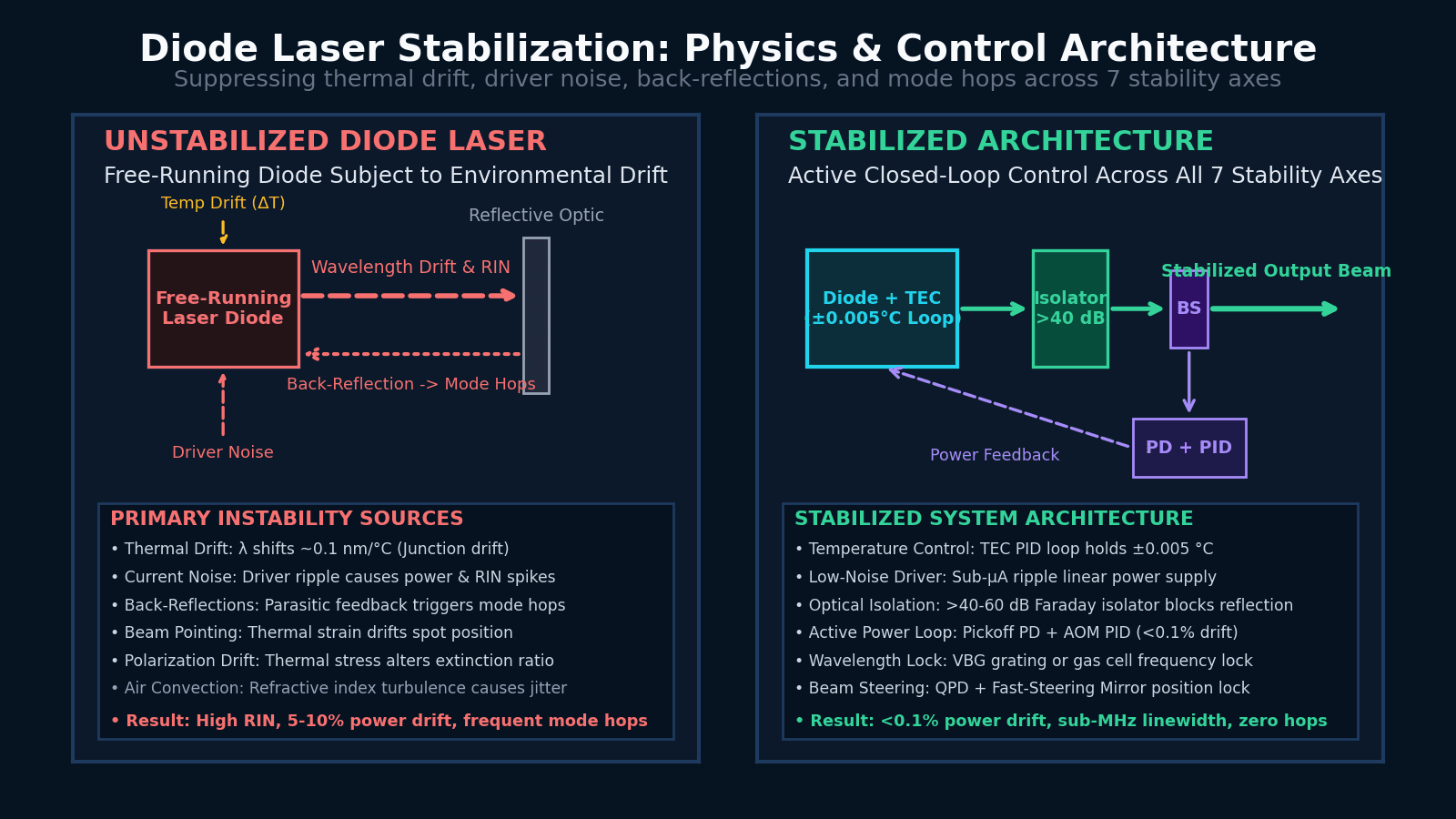
Why diode lasers drift or become noisy, how to identify the physical source of instability, and how to choose an appropriate stabilization architecture across 7 stability axes.

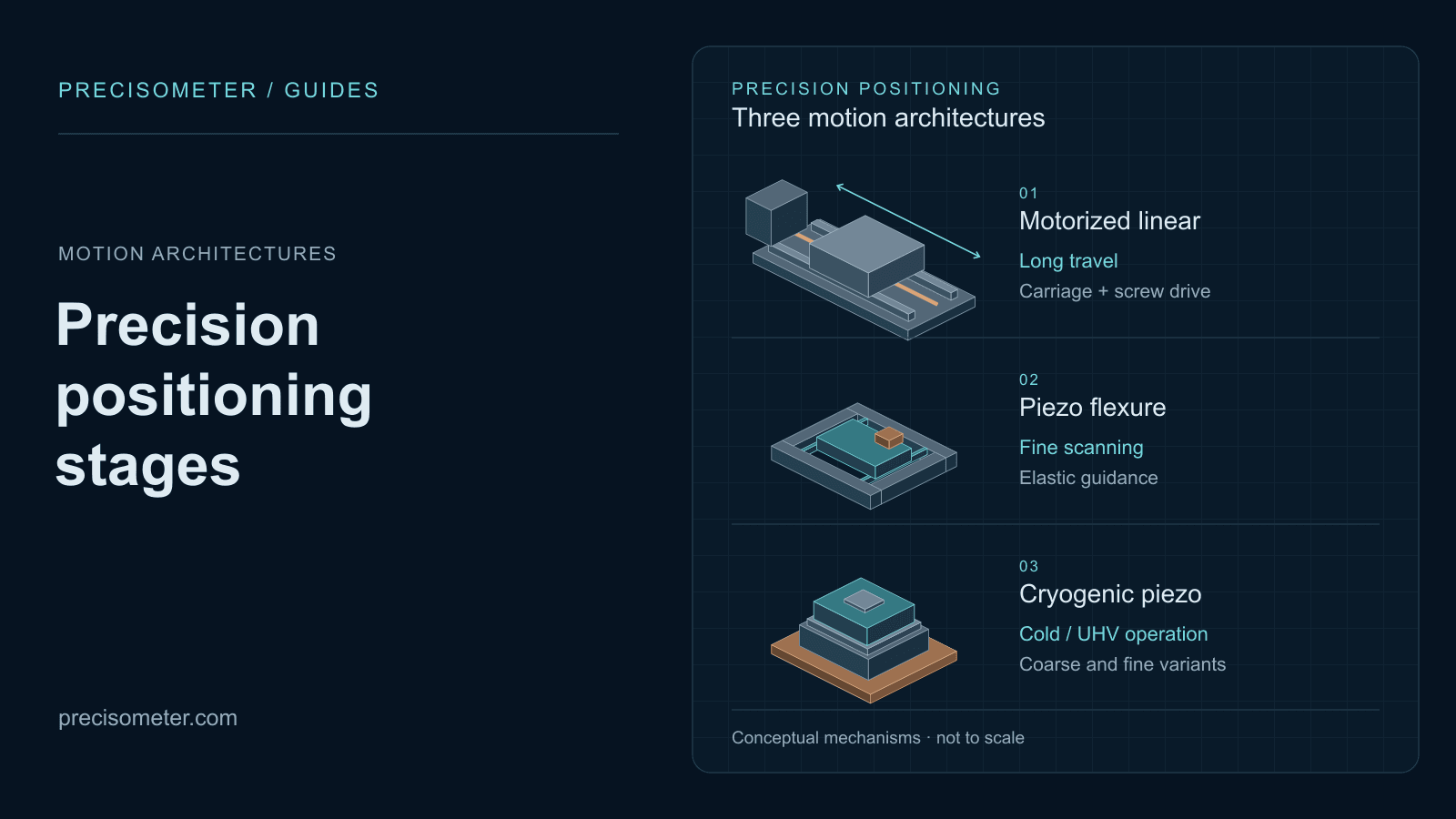
Match travel, resolution, speed, load, vacuum, temperature, and magnetic field requirements to motorized linear, ambient piezo, or cryogenic piezo positioning architectures.

Match spectral width, instantaneous linewidth, coherence length, mode-hop-free tuning, and power requirements to FP, DFB, DBR, VBG-locked, or ECDL semiconductor architectures.