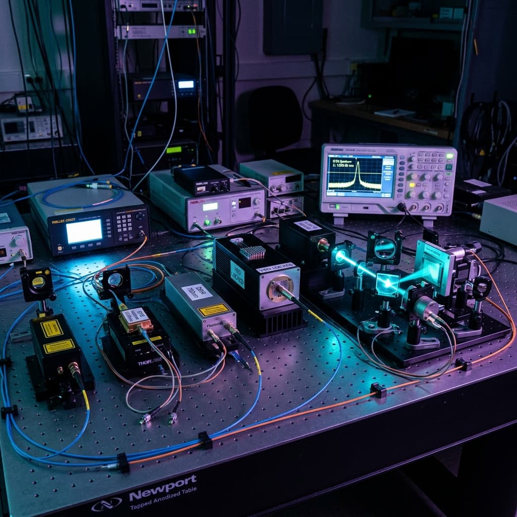
Choosing Between FP, DFB, DBR, VBG-Locked, andExternal-Cavity Diode Lasers
No semiconductor laser architecture is universally superior. Match total spectral width, instantaneous linewidth, coherence length, mode-hop-free tuning, and optical feedback sensitivity to what your measurement physically detects.
From broad FP multimode to sub-MHz ECDL single frequency
Short-coherence FP to multi-kilometer phase survival
Sub-MHz ECDL single mode to free-running FP comb
Thermal DFB tuning to piezo-driven ECDL grating sweeps
1. Begin with Diode-Laser Cavity Fundamentals
Semiconductor diode lasers operate via stimulated recombination of electron-hole pairs across a PN junction. The physical cavity design dictates whether the emission consists of dozens of oscillating longitudinal modes or a single, sub-MHz frequency line.
The optical frequency width ($\Delta \nu$) of a single longitudinal mode over a short measurement window. Binds coherence length ($L_c \approx c / (\pi \Delta \nu)$) and interferometric phase noise.
The full width of the emission envelope containing all oscillating modes. For a multimode Fabry-Pérot diode, the envelope is 1.5–3.0 nm wide, even if each individual comb mode is narrow.
The intensity ratio between the dominant single frequency peak and the strongest suppressed side mode. True single-frequency lasers (DFB/ECDL) require SMSR > 50 dB.
The 14 Semiconductor Laser Physics Parameters:
Optical amplification provided by electron-hole recombination in quantum wells.
Resonant structure formed by cleaved semiconductor facets, Bragg gratings, or external mirrors.
Discrete standing waves satisfying m λ = 2 n L. Spaced by Free Spectral Range.
Frequency spacing between adjacent cavity modes: Δν_FSR = c / (2 n_g L).
Spectral envelope over which semiconductor gain exceeds cavity loss (~20–40 nm).
Drive current where optical gain balances cavity round-trip losses.
Bandgap shrinkage causing ~0.25–0.3 nm/°C wavelength shift in FP diodes.
Abrupt wavelength jumps as temperature/current shifts the dominant mode.
Slow drift of peak emission wavelength caused by heatsink temperature shifts.
Maximum optical path difference where interference fringes survive.
Instability & RIN degradation caused by back-reflections into the laser cavity.
Intensity fluctuations in dB/Hz, binding optical trapping & balanced detection.
Spatial transverse mode profile (M² < 1.1 for single-mode fiber coupling).
Ratio of linear TE to TM polarization components (>20 dB).
Compare the 5 Diode Laser Architectures
Click a technology tab to inspect cavity feedback mechanisms, strengths, limitations, and suitable applications.
Distributed-Feedback (DFB) Diode Lasers
DFB lasers integrate a diffraction grating directly along the active gain region of the semiconductor chip. This distributed Bragg feedback forces the laser to oscillate on a single dominant longitudinal mode with high side-mode suppression ratio (SMSR > 50 dB) and long coherence length (>10 m).
- • True Single Frequency: Extremely high spectral purity (SMSR > 50 dB).
- • Monolithic Butterfly Module: Integrated TEC, thermistor, photodiode, & fiber pigtail.
- • Fast Current Modulation: High modulation bandwidth for telecom & gas sensing (>10 GHz).
- • Long Coherence Length: Coherence lengths from 10 m to >100 m for interferometry.
- • Restricted Wavelength Availability: Gratings fabricated for specific sensing wavelengths.
- • Limited Tuning Range: Thermal tuning ~0.08 nm/°C over 2–3 nm total range.
- • Wavelength Chirp: Direct current modulation induces frequency chirp.
- • Driver Noise Sensitivity: Driver current noise translates directly into frequency jitter.
7. Comprehensive 18-Parameter Matrix
Side-by-side technical comparison of Fabry–Pérot, DFB, DBR, VBG-Locked, and External-Cavity Diode Lasers.
| Parameter | Fabry–Pérot (FP) | DFB Diode | DBR Diode | VBG-Locked | ECDL |
|---|---|---|---|---|---|
| Cavity & Feedback | Cleaved Chip Facets | Internal Distributed Grating | Passive End Bragg Section | External VBG Glass Element | External Grating (Littrow/LM) |
| Longitudinal Modes | Multiple Comb Modes | Single Dominant Mode | Single Dominant Mode | Narrowed Envelope / Multimode | Single Ultra-Narrow Mode |
| Total Spectral Width | 1.5 – 3.0 nm (>500 GHz) | <0.001 nm (Single mode) | <0.001 nm (Single mode) | 0.05 – 0.15 nm (30–80 GHz) | <0.000001 nm (Sub-MHz) |
| Instantaneous Linewidth | >100 MHz (per mode) | 1 – 10 MHz | 1 – 5 MHz | >100 MHz (multimode cluster) | <100 kHz (<10 kHz locked) |
| Coherence Length | 0.1 – 1 mm | 10 m to >100 m | 10 m to >50 m | 1 – 10 mm | >1 km |
| Center-Wavelength Drift | High (~0.25 nm/°C) | Low (~0.08 nm/°C) | Low (~0.08 nm/°C) | Very Low (±0.01 nm) | Ultra-Low (Locked) |
| Mode-Hop-Free Tuning | Limited by mode hops | 2 – 3 nm (Thermal) | 3 – 5 nm (Electronic) | None (Locked wavelength) | >50 GHz (Piezo + Current) |
| Total Tuning Range | Thermal gain shift | 2 – 3 nm | 5 – 10 nm | Fixed by VBG | >30 nm |
| Max Output Power | Very High (>1 W) | Moderate (50 – 150 mW) | Moderate (50 – 200 mW) | High (100 – 500+ mW) | Moderate (20 – 100 mW) |
| Intensity Noise (RIN) | Moderate | Very Low (−150 dB/Hz) | Very Low (−145 dB/Hz) | Low | Ultra-Low (−160 dB/Hz) |
| Modulation Capability | Direct Current High-Speed | High Bandwidth (>10 GHz) | Multi-Section Current | Limited | Current + Piezo |
| Optical Feedback Sensitivity | High | Very High (Needs Isolator) | Very High (Needs Isolator) | Moderate | Extreme (Needs >60dB Isolator) |
| Temperature Sensitivity | High | Moderate (TEC Controlled) | Moderate (TEC Controlled) | Low (VBG Locked) | Moderate |
| Mechanical Sensitivity | Low | Low (Monolithic) | Low (Monolithic) | Low to Moderate | High (Vibration sensitive) |
| Size & Integration | Compact (TO-can) | Compact (Butterfly) | Compact (Multi-pin) | Compact Module | Larger Benchtop Head |
| Relative Cost | Lowest (€) | Moderate (€€) | Moderate to High (€€€) | Moderate (€€) | High (€€€€) |
| Best Application | Fluorescence & Pumping | Gas Sensing & Telecom | Tunable Spectroscopy | Raman Spectroscopy | Atomic & Quantum Physics |
| Main Limitation | Broad envelope & mode hops | Restricted tuning range | Driver complexity | Short coherence length | Vibration sensitivity & cost |
8. Application-Led Recommendations
How to select the right architecture based on what your optical measurement physically detects.
Spontaneous Raman depends on spectral width of the complete emission envelope rather than kHz linewidth. VBG locking delivers 100–500 mW power at <0.08 nm width without paying for single-frequency DFB/ECDL chips.
Interferometry measures optical phase difference. A VBG-locked or FP diode has insufficient coherence (<1 cm), causing fringe contrast washout. Use a true single-frequency DFB or DBR laser.
Fluorophore absorption bands are 20–50 nm wide. The fluorophore does not care about phase coherence or MHz linewidth. FP diodes provide maximum power and efficiency at lowest cost.
Atomic transitions (e.g. Rubidium D2 line at 780.24 nm) have natural linewidths of ~6 MHz. An ECDL delivers <100 kHz linewidth and continuous piezo tuning required for Doppler cooling.
Pumping solid-state lasers or fiber lasers requires raw photon flux. Paying for single-frequency narrow linewidth adds expense without improving pump absorption.
Tunable Diode Laser Absorption Spectroscopy (TDLAS) sweeps a single frequency line across gas absorption peaks (e.g. CH4, CO2) using fast current modulation.
9. Laser Datasheet Red Flags
10 common datasheet marketing claims that lead to incorrect diode laser selection.
Quoting 10 kHz linewidth over 1 µs, but thermal jitter broadens it to 10 MHz over 1 second.
VBG locking narrows the envelope (~0.08 nm) but contains multiple comb modes and short coherence.
Quoting 1 MHz mode linewidth for an FP diode whose total output spans 500 GHz.
Claiming 10 nm tuning range, but the laser mode hops every 0.1 nm.
Quoting ±0.01 nm stability in a temperature-controlled lab, but drifting 0.5 nm in the field.
SMSR is 50 dB at max current, but drops to 20 dB at low drive current.
Linewidth is 1 MHz at 10 mW, but broadens to 10 MHz at maximum 100 mW power.
Omitting sensitivity to back-reflections; laser mode hops when coupled into fiber.
Wavelength drifts for 30 minutes after power-on before reaching thermal equilibrium.
Wavelength accuracy is ±0.5 nm, even if short-term stability is ±0.001 nm.
Diode Architecture Lab
Select your experimental parameters to determine the exact diode laser architecture, spectrum profile, and supporting components.
1. Input Experimental Parameters
2. Recommended Architecture & Rationale
Volume-Bragg-Grating (VBG) Locked Diode Laser
Spontaneous Raman spectroscopy and narrowband optical pumping require high output power (100–500 mW) combined with a stable total emission envelope (<0.1 nm / <0.05 nm). A VBG glass element provides narrow optical feedback, locking the center wavelength against thermal drift without requiring expensive single-frequency DFB/ECDL chips.
CRITICAL NUANCE: A VBG-locked diode is NOT automatically a single-frequency laser. Its coherence length is typically millimeters (not meters), making it unsuitable for long-path interferometry despite its narrow spectral envelope.
Recommended Supporting Components:
- •Low-Noise Diode Current Driver with soft start
- •TEC Temperature Controller
- •Bandpass Clean-Up Optical Filter (for ASE suppression)
- •Fiber Optic Collimator
11. 8-Step Selection Workflow & Decision Tree
Follow this systematic 8-step engineering sequence to route your setup to the simplest architecture that satisfies your binding requirement.
Does the detector measure optical phase, frequency, spectral intensity, or raw power?
Is total envelope width (<0.08 nm vs >1.5 nm) critical for spectroscopy bandpass?
Does phase interference require >10 m coherence or sub-MHz linewidth?
Is fixed wavelength sufficient, or is continuous mode-hop-free tuning required?
Define delivered power after isolators, filters, and fiber coupling optics.
Assess vibration, temperature swings, and back-reflection feedback sensitivity.
Choose the simplest architecture (FP < VBG < DFB < DBR < ECDL) that satisfies specs.
Qualify current driver noise, TEC stability, and warm-up time under actual lab conditions.
Compact Diode Laser Routing Tree:
→ Select Fabry–Pérot (FP) Diode.
→ Select VBG-Locked Diode Laser.
→ Compare DFB and DBR Diode Lasers.
→ Select External-Cavity Diode Laser (ECDL).
12. 6 Worked Engineering Decision Examples
Case studies illustrating architecture selection, binding specs, and supporting components.
13. Verified Product Ecosystem Integration
Explore verified semiconductor diode lasers, low-noise current drivers, TEC controllers, and optical isolators.
Semiconductor Diode Lasers →
FP, DFB, VBG-locked, and narrowband diode lasers covering UV, visible, NIR (785, 808, 852, 1064 nm), and SWIR.
Laser Accessories & Drivers →
Ultra-low noise current drivers, precision TEC temperature controllers, optical isolators, and fiber collimators.
Spectrographs & Wavelength Meters →
High-resolution spectrographs and optical spectrum analyzers for verifying emission width, SMSR, and laser drift.
14. Frequently Asked Questions
What is the difference between DFB and DBR lasers?↓
Is a VBG-locked laser single-frequency?↓
Which diode laser has the narrowest linewidth?↓
Do I need an ECDL for Raman spectroscopy?↓
Which diode laser is best for interferometry?↓
Is an FP diode suitable for fluorescence?↓
What causes mode hopping?↓
How does temperature affect diode-laser wavelength?↓
What is mode-hop-free (MHF) tuning?↓
Does narrow linewidth always mean long coherence?↓
Can a DFB laser be frequency locked?↓
Why is optical isolation important?↓
Should I choose a diode laser based on linewidth or spectral width?↓
Which architecture is best for atomic physics?↓
Further Photonics Reading
Related Laser & Spectroscopy Guides
 Photonics
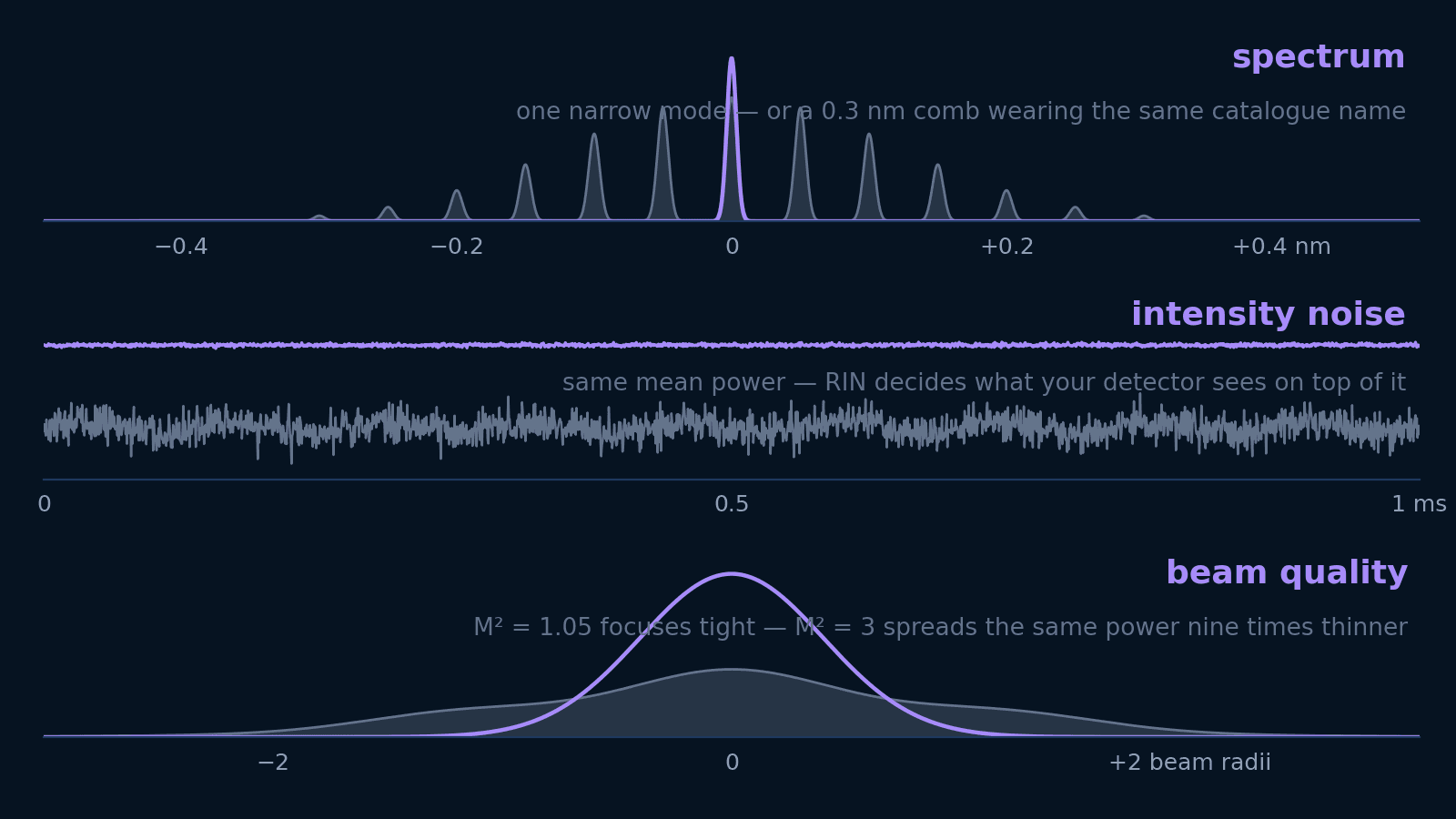
Laser specifications decoded
Linewidth, spectral width, RIN, M², and coherence length answer five different questions. Translate each into the units your experiment is designed in — and learn which ones not to pay for.
Open guide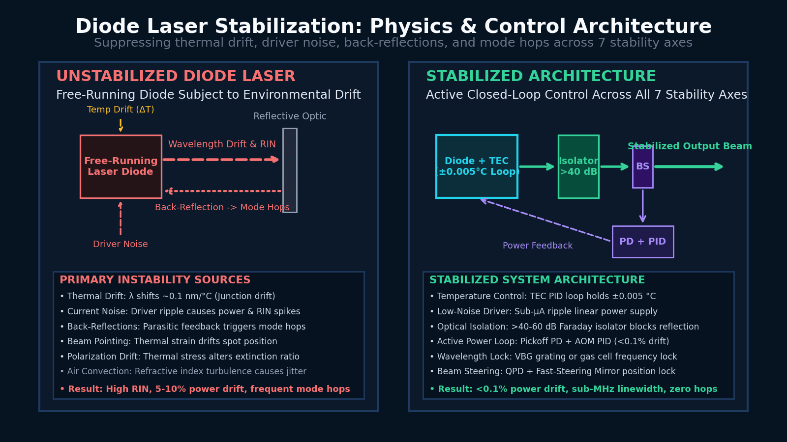 Photonics
How to stabilize a diode laser
Why diode lasers drift or become noisy, how to identify the physical source of instability, and how to choose an appropriate stabilization architecture across 7 stability axes.
Open guide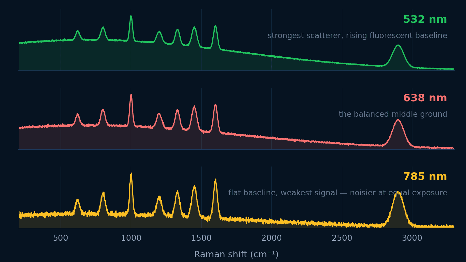 Raman spectroscopy
Choosing a Raman excitation wavelength
Balance the ν⁴ signal law, fluorescence background, silicon detector cutoff, and spatial resolution across 532, 638, and 785 nm.
Open guide