Back to Home
← All guides

Motion control · 20 min

Motorized linear stage selection

Travel, load, speed and accuracy are on every datasheet. Three of them interact in ways the datasheet never mentions, and the number that decides your real accuracy is usually not printed on it at all.

Moment loadingAbbe errorEncoder placementVelocity profilesSettle time

Start here

Four numbers, and what each one is not telling you.

A stage datasheet leads with travel, load capacity, maximum speed and positioning accuracy. Every one of those figures is true, and every one of them is measured under conditions that are not yours. Load is quoted centred and vertical. Speed is quoted as a maximum you may never reach. Accuracy is quoted at the platform, not at the point in space you actually care about.

The consequence is a specific and very common failure: a stage that meets its specification and misses your requirement by a factor of five. Not because anyone lied, but because the payload sits on a bracket 80 mm off the guide centre, the optic is 100 mm above the carriage, and neither of those distances appears anywhere in the purchase decision.

So the useful sequence is to work backwards from your work point. Where is the thing being positioned, relative to the guide? What moment does your payload apply? How far do you actually move, and how often? Answer those first and the stage almost specifies itself — and frequently the answer is a different guide geometry rather than a more expensive screw.

Reading the datasheet

What is quoted, and what to ask for instead.

SpecificationWhat is quotedWhat it hidesAsk for this instead
TravelFull stroke, in mmPositioning error and thermal expansion both scale with itUsable travel after limit switches and hard stops, and the accuracy grade over that length
Load capacityNormal (centred, vertical) load, in kgMoment capacity is almost always the real limitPitch, yaw and roll moment ratings, and the angular deflection per N·m
SpeedMaximum velocity, in mm/sUnreachable below a crossover distance set by accelerationAcceleration, and settle time to tolerance with your payload fitted
AccuracyPositioning accuracy and repeatabilityMeasured at the platform, not at your work pointWhether the figure is uni- or bidirectional, and the pitch/yaw error over travel

Interactive

Build the error budget at your work point.

Set the mechanism, the feedback, and — critically — where your payload and your work point actually sit. The panel identifies which term dominates, which is usually not the one the purchase decision was made on. Try switching the feedback between a rotary and a linear encoder and watch how little the rotary one changes.

Accuracy budget lab

Which error term is actually in charge

Datasheets quote positioning accuracy and repeatability. Neither includes the two terms that usually dominate a real installation — where your work point sits, and what your payload does to the guide.

Drive and guide

The industrial workhorse. Long travel, high load capacity, and preloaded ball nuts bring backlash to a few micrometres. Straightness is limited by the rail, not the screw.

Position feedback

Confirms the motor turned. It sits upstream of the screw and the coupling, so it sees neither pitch error nor backlash. Commonly mistaken for closed-loop positioning; it is closed-loop velocity control.

200 mm

Pitch error and thermal expansion both scale with this.

5.0 kg

Mass alone is harmless. Mass on a lever arm is not.

80 mm

Distance from the guide centre to the payload CG. This is what creates the moment.

100 mm

Guide plane to the point you actually care about — the focus, the probe, the tool.

1.0 K

Over the measurement. A lab without control drifts more than this.

10.0 µm

What the application needs at the work point.

Total error at the work point

40.7 µm

Against a 10.0 µm requirement — over by 30.7 µm.

Positioning / pitch errordominant20.0 µm
Backlash3.00 µm
Abbe error15.4 µm
Thermal2.34 µm

Payload moment

3.92 N·m

5.0 kg at 80 mm

Total angular error

31.8″

11.8″ from payload

Abbe multiplier

0.48 µm/″

per arcsecond of tilt

What to fix first

Screw pitch error dominates at 20.0 µm. A linear encoder on the platform would largely remove this. Note that a rotary encoder on the motor would not: it cannot see the screw.

Representative coefficients by mechanism class, not measurements of a specific model — take pitch error, backlash and angular deviation from the datasheet of the stage you are actually quoting. Terms are summed linearly because all four are systematic and can align, which makes this a worst-case budget. Straightness and flatness of travel, guide wear, cable drag and controller quantisation are not modelled.

Drive and guide

Four combinations that cover almost everything.

DriveGuideBacklashSpeedWhere it belongs
Lead screwDovetail or plain slide20–50 µmLowSelf-locking and inexpensive, so it holds position vertically with no brake. Friction and backlash make it a set-and-forget adjustment mechanism rather than a scanning axis.
Ball screwRecirculating ball guide2–5 µm preloadedModerate to highThe industrial default. Long travel, high load, decent speed. Not self-locking, so a vertical axis needs a brake — check that before mounting it upright.
Ball screwCrossed roller1–3 µm preloadedModerateLine contact rather than point contact gives much higher moment stiffness and better straightness. Shorter travel, and the geometry to choose when the payload is cantilevered.
Linear motorCrossed roller or ball guideNoneVery highNo screw at all — nothing to wear, nothing to backlash, and acceleration a screw cannot approach. Needs a linear encoder by construction, is never self-locking, and dissipates heat into the stage.

Load is a moment specification

A 5 kg payload centred on the platform is a 5 kg payload. The same 5 kg on a bracket 80 mm out is a 3.9 N·m moment, and it will tilt the carriage by an amount set by the guide’s moment stiffness — which then multiplies straight into Abbe error at your work point.

This is why load capacity and accuracy are the same question, and why crossed-roller guides justify their cost on cantilevered payloads. Ask for pitch, yaw and roll moment ratings, not just the kilogram figure.

Duty cycle is a drift specification

A steel drive train expands about 11.7 ppm per kelvin, so 200 mm of travel moves roughly 2.3 µm per kelvin — larger than the repeatability of a good stage. Friction at the nut heats the screw, and a linear motor dumps its coil losses straight into the stage.

So a stage running hard drifts even in a controlled room. If you work at micrometre level, let it reach equilibrium, and re-reference against a fixed datum rather than trusting an absolute coordinate taken hours ago.

Interactive

Find out whether your speed specification does anything.

Enter the move you actually make rather than the full travel. Below a crossover distance the stage never reaches its rated velocity, and acceleration plus settle time decide throughput entirely — which is the regime most step-and-repeat automation lives in.

Move time and throughput lab

Whether your top-speed specification does anything at all

Set your actual move distance rather than the full travel. Below a crossover distance the stage never reaches its rated speed, and the number you bought on stops mattering.

Typical duty

Short indexing moves, thousands per run. Almost pure acceleration and settle — the cruise phase never happens.

10 mm

The move you actually make, not the stage's full travel.

100 mm/s

The headline datasheet figure. Watch how often it goes unused.

500 mm/s²

Rarely quoted, usually the real limit. Screw inertia caps this; a linear motor does not.

100 ms

Ringing down to within tolerance. Almost never on a datasheet, and often the largest term.

Cycle time per move

383 ms

9,403 moves per hour at 100 % duty.

Accel + decel 283 msCruise 0 msSettle 100 ms

Velocity profile

Triangular

never reaches rated speed

Peak velocity reached

71 mm/s

71 % of rated

Settle share of cycle

26 %

time spent not moving

What is actually limiting you

This move is triangular: it accelerates to 71 mm/s and immediately decelerates, never touching the rated 100 mm/s. Any move shorter than 20.0 mm is in the same regime. Paying for more top speed changes nothing here — acceleration and settle time are the only levers, and a direct-drive stage is where both improve.

The crossover is 20.0 mm. Below that distance the rated speed is unreachable by geometry. Compare it against your real move distribution before choosing a stage on velocity — for step-and-repeat work the crossover is usually far longer than any move you make.

Idealised trapezoidal profile with symmetric acceleration and deceleration, no jerk limiting, and settle treated as a fixed interval. Real controllers apply S-curve profiles that lengthen the move slightly and shorten the settle; real settle time depends strongly on payload mass and on how well the servo is tuned to it. Duty-cycle heating of screw and motor is not modelled and will limit sustained throughput below the figure shown.

From the catalogue

Families, and what each one is actually for.

Ordered by the problem they solve rather than by price. Repeatability and load figures are the published class values for each family — confirm the exact grade for the travel and motor option you configure.

LMA-TR-100 … LMA-TR-600

Linear motor with integral scale Metrology on the platform
  • 100–600 mm travel
  • Built-in grating ruler
  • No screw, no backlash
  • G10 and E10 grades

Direct drive with the encoder built into the mechanism, which is the only arrangement where the phrase positioning accuracy means what buyers assume it means — the metrology is on the moving platform, so screw error and backlash do not exist to be corrected. This is also the family to reach for when acceleration rather than top speed governs your cycle time, which the throughput panel above shows is most step-and-repeat work.

CXP · CXPF series

Crossed roller, high moment stiffness
  • 15–100 mm travel
  • Crossed-roller guide
  • ±0.5 µm repeatability
  • CXPF flanged for larger platforms

The answer when the accuracy budget is dominated by Abbe error rather than by the screw. Crossed-roller guideways carry moment loads far better than recirculating ball guides of the same size, so an offset or cantilevered payload tilts the platform much less — and it is that tilt, multiplied by your work-point offset, that usually sets the real error.

KA series

Steel, high load
  • 50–1000 mm travel
  • Recirculating ball guide
  • Up to 50 kg class horizontal
  • ±1–2 µm repeatability

Steel construction and a recirculating ball guide for genuinely heavy payloads over long travel, with vertical Z variants in the same family. Note the load figure is a horizontal, centred rating — if your mass sits on an arm, work the moment out before assuming the number applies. Available with stepper bundles, servo packages or motor-plus-encoder configurations.

PA series

Cost-effective aluminium
  • 50–400 mm travel
  • 15–30 kg horizontal class
  • ±3 µm repeatability
  • Covered C variants

The volume option, and the right one when the axis positions something rather than measures it — sample handling, source translation, coarse approach under a finer stage. At ±3 µm repeatability it is not a metrology axis, and pairing it with a piezo for the last micrometre is usually cheaper than buying accuracy in the coarse stage.

LAK series

Submicron, low profile
  • 20–60 mm travel
  • Crossed-roller or slider guide
  • Submicron step resolution
  • Low-profile aluminium

Compact submicron positioning where height above the table matters — a low profile directly shortens the Abbe arm between the guide plane and your optic, which is one of the few ways to reduce that error term without spending anything. Well matched to optical alignment work with modest payloads.

UFS · LA series

Compact and industrial
  • 20–100 mm travel
  • Precision screw drive
  • LA: ±1.5 µm repeatability
  • 60 mm width footprint

Small-footprint stages for optical alignment (UFS) and compact industrial automation with a recirculating slide guide (LA). Both are screw-driven, so the feedback question from the accuracy panel applies: without a linear encoder on the platform, the quoted repeatability describes the mechanism and not your work point.

Most families are available with stepper bundles, servo packages, or motor-plus-encoder configurations, and in left- or right-handed and reinforced-frame variants. Tell us the travel, the payload and where its centre of gravity sits, the move distribution, and the accuracy you need at the work point — that is enough to size the axis properly.

The rest of the axis

A stage is never the whole answer.

Controllers and drives

The stage is half the axis. What drives it decides whether you get the acceleration, the settle time and the feedback the mechanism is capable of.

  • Motion control

    Stepper, servo and linear-motor controllers, multi-axis synchronisation and the driver cards that go with each stage family.

  • Full motion catalogue

    Every linear, rotation, vertical and goniometer stage, with the motor and encoder options for each.

  • Stage finder

    Filter by travel, load, resolution and environment instead of reading through model numbers.

  • Piezo controller board

    For closing a fine axis against your own detector signal rather than against a stage encoder.

One question that settles a surprising number of specifications: where is the encoder? A rotary encoder on the motor shaft closes the loop on velocity, not on position — it sits upstream of the coupling, the screw and the nut, so it cannot see pitch error or backlash. Only a linear encoder on the moving platform makes the accuracy figure describe the platform.

Building the axis stack

Coarse travel and fine resolution rarely come from the same mechanism. Most real axes are two stages, and the interface between them is where accuracy is lost.

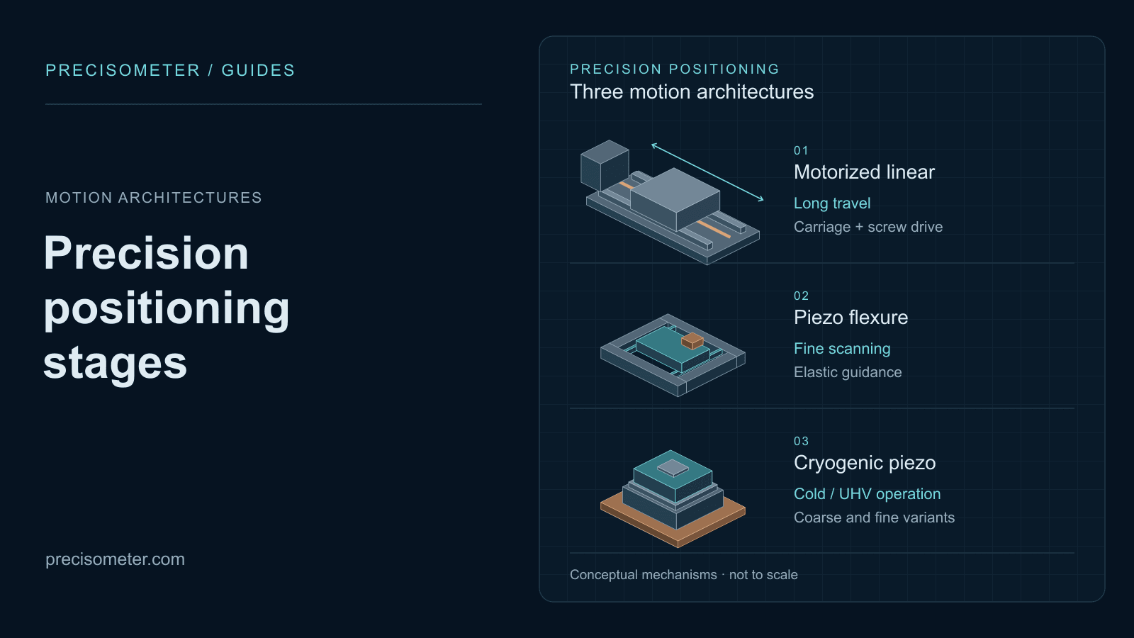
  • Piezo stages and nanopositioners

    The fine axis on top: micrometres of travel at nanometre resolution, where a screw cannot reach.

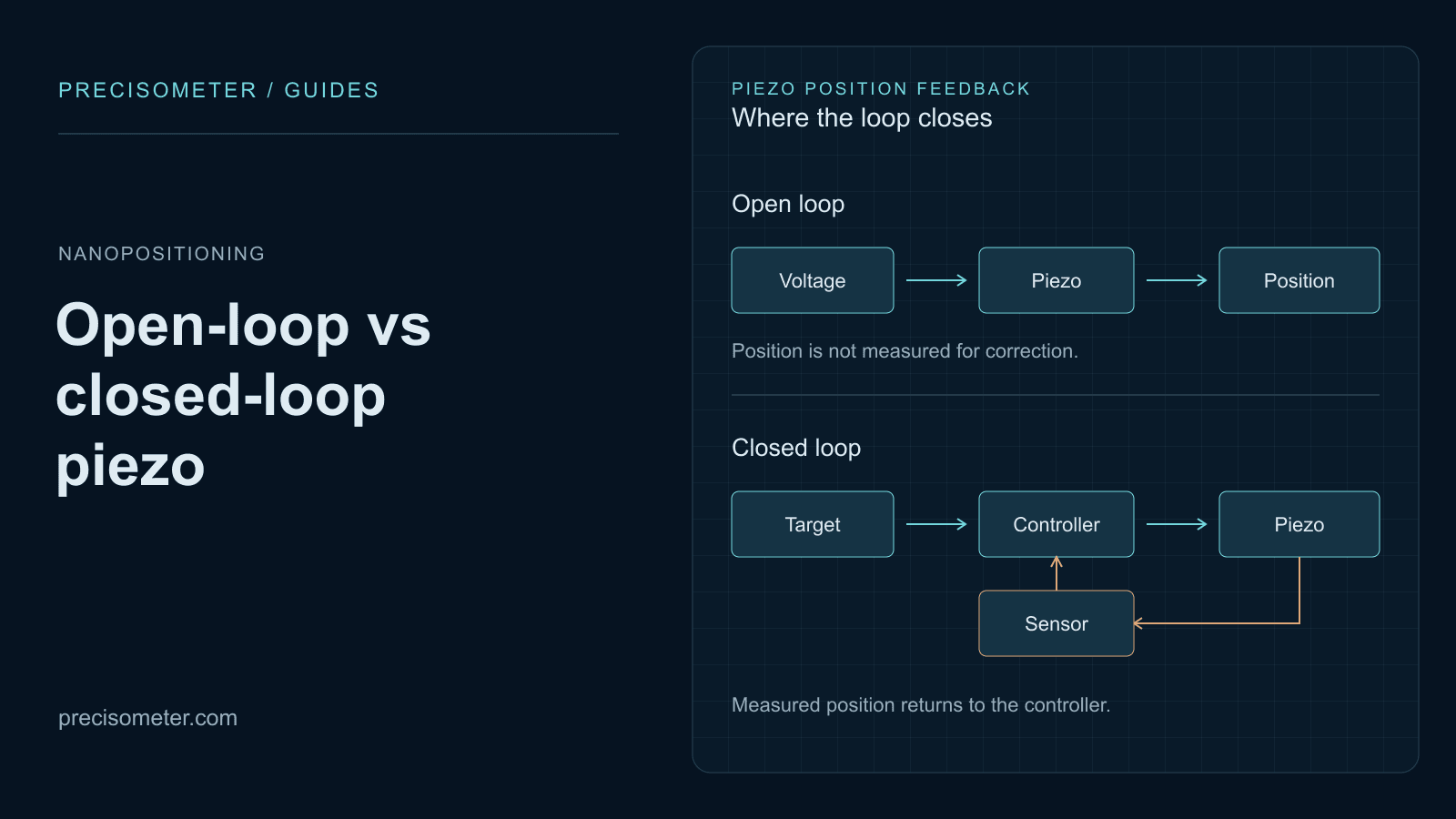
  • Open-loop vs closed-loop piezo

    Which feedback strategy the fine axis needs, and what a servo costs you in bandwidth.

  • Manual stages

    For axes aligned once at build time and never scanned — cheaper and stiffer than motorising something you will not move.

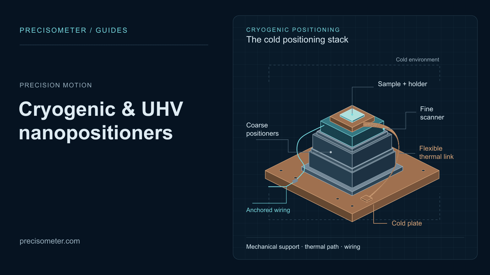
  • Cryogenic piezo stages

    When the axis has to work cold, where lubricants, thermal contraction and outgassing rule out most motorised stages.

  • Fibre alignment stages

    The canonical coarse-plus-fine problem, with dedicated hardware for the capture-range half.

What the stage sits on

Positioning accuracy is measured relative to the stage body. Everything underneath it moves too, and none of that is in the specification you bought.

  • Optical tables and breadboards

    The datum for the whole axis. A table that flexes under the stage undoes the guide specification.

  • Optical cage system

    Rigid pre-aligned mounting for the optics the stage carries, with fewer joints to drift.

  • Mirror mounts

    Frequently the softest element in the loop — a stiff stage under a compliant mount is a compliant axis.

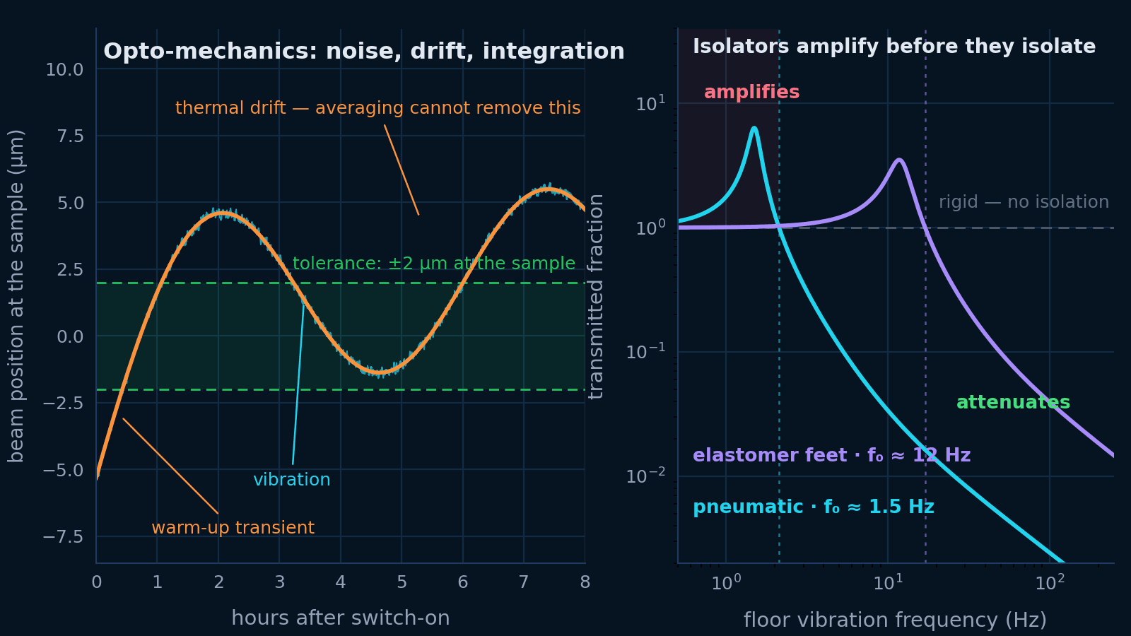
  • Opto-mechanics rig guide

    The vibration and thermal-drift budget that sits around everything on this page.

Common questions

The questions that decide the order.

What load capacity do I actually need?

Almost certainly less than you think in kilograms, and almost certainly more than you think in newton-metres. Datasheets quote a normal load capacity — mass sitting centred on the platform, pressing straight down into the guide. Real payloads sit on brackets, off to one side, or cantilevered forward, and that offset turns mass into a moment. A 5 kg payload whose centre of gravity is 80 mm from the guide centre applies about 3.9 N·m, and it is the moment rating and the angular deflection per newton-metre that tell you whether the stage can hold it. Ask for the pitch, yaw and roll moment ratings; a stage with plenty of normal capacity can be well outside its moment envelope.

Why is my stage less accurate than its datasheet says?

Usually because the datasheet describes the platform and you care about somewhere else. Angular error — pitch and yaw of the carriage as it travels — turns into a linear error at your work point in proportion to the distance between them. This is Abbe error, and it is simply the angle multiplied by the offset. Twenty arcseconds is a routine figure for a good guide, and at a 100 mm offset that is about 10 µm, which comfortably exceeds the ±1 to 2 µm repeatability on the front of the datasheet. Nothing in the drive train fixes it. You reduce it by shortening the offset, or by choosing a guide with better angular performance and higher moment stiffness.

Is a rotary encoder on the motor closed-loop positioning?

No, and this is the most consequential misunderstanding in motion specification. A rotary encoder on the motor shaft measures how far the motor turned. It sits upstream of the coupling, the screw and the nut, so it cannot see screw pitch error, it cannot see backlash, and it cannot see thermal expansion of the screw. What it gives you is reliable velocity control and confirmation that you have not lost steps — genuinely valuable, and not the same thing as knowing where the platform is. Only a linear encoder mounted on the moving platform puts the mechanical path inside the control loop.

Do I need a linear encoder?

If you need absolute positioning accuracy at the micrometre level, or you reverse direction frequently and cannot afford backlash, then yes. If your axis positions something to a coarse tolerance and a finer stage does the precision work, then no — and the money is better spent on the fine axis. A useful test is whether you can always approach from the same direction. Unidirectional repeatability excludes backlash and is often several times better than the bidirectional figure, so a well-planned motion sequence can buy much of what an encoder would.

How fast will my stage actually move?

For short moves, considerably slower than the top-speed figure suggests, because it never reaches it. A point-to-point move accelerates, optionally cruises, then decelerates. If the move is shorter than twice the acceleration distance — v²/a — the profile is triangular and the rated velocity is unreachable by geometry. A stage rated at 100 mm/s with 500 mm/s² of acceleration needs 20 mm just to reach and leave top speed, so every move below that is acceleration-limited. For step-and-repeat work, acceleration and settle time decide throughput and the velocity specification is close to irrelevant.

What is settle time and why is it never on the datasheet?

It is the interval between the controller declaring the move complete and the platform actually being inside your tolerance band — the ringing at the end of the move dying away. It is absent from most datasheets because it is not a property of the stage alone: it depends on your payload mass, how rigidly you mounted it, the servo tuning and the tolerance you demand. That also makes it the specification worth insisting on, measured with your payload fitted and your tolerance stated. In short-move automation it is frequently the largest single term in the cycle.

Can I mount a linear stage vertically?

Sometimes, and the drive type decides. A lead screw is self-locking and will hold its position with power removed, which is why economy vertical stages usually use one. A ball screw is efficient enough to back-drive under load, so a vertical ball-screw axis needs a motor brake or it drops when power is cut. A linear motor has no self-locking behaviour whatsoever and always needs a brake or a counterbalance. Load capacity also falls when the guide is loaded along its weak axis, so use the vertical rating rather than the horizontal one — many families publish dedicated Z-axis variants for exactly this reason.

How much does temperature move a motorized stage?

More than most error budgets allow for. A steel drive train expands about 11.7 parts per million per kelvin, so 200 mm of travel moves roughly 2.3 µm per kelvin — comparable to or larger than the repeatability of a good stage. A screw-driven stage also heats itself through friction at the nut, and a linear motor dissipates its coil losses directly into the stage, so duty cycle produces drift even in a stable room. If you are working at the micrometre level, let the system reach thermal equilibrium before measuring, and re-reference against a fixed datum rather than trusting an absolute position taken hours earlier.

Primary sources

Tell us where the work point is. We will size the axis around it.

Travel, payload mass and where its centre of gravity sits, the offset from the guide to your work point, your move distribution and the accuracy you need there — that is enough for us to come back with a drive, a guide geometry, a feedback strategy and a controller that can service it.

  • Accuracy specified at your work point, not the platform
  • Load checked as a moment, not a mass
  • Throughput modelled from your real move distances