Complete rig guide
Building a stable opto-mechanical rig
Vibration, thermal drift and mechanical integration are one problem, not three. Budget them at the sample — then buy the table, the mounts and the beam height that budget asks for.
Noise is a spectrum
Not a single number. What matters is how much motion sits at the frequencies your isolation actually rejects.
Drift is thermal
Slow, monotonic, immune to averaging, and caused by materials expanding — which no mount quality can prevent.
The rig is one loop
Source, mounts, table and detector form a mechanical circuit. Its weakest member sets the performance of all of them.
The decision in one sentence
Name the motion you can tolerate at the sample, then work outward.
Nobody buys a rig — they buy a table, some mounts and a handful of posts, and hope the assembly is stable. It usually is not, because stability is a property of the whole mechanical loop and the loop was never specified. One number fixes that: how far the beam may move at the sample, and over what time.
Set the tolerance
A fraction of the spot, the fiber core, the pinhole, or the wavelength — whichever is smallest.
List the loop
Every component the beam depends on, its length, and its material.
Allocate the budget
Split the tolerance between pointing, thermal drift and vibration. Then spend where the budget is tightest.
1 · The error budget
Angle times distance. That is the whole mechanism.
A mirror mount does not move the beam — it tilts it, and the lever arm downstream does the moving. This is why the same mount is excellent in a compact assembly and hopeless across a three-metre path, and why the fix for a wandering beam is more often geometry than component quality.
1 µrad · 100 mm
0.2 µm at the sample
1 µrad · 1 m
2 µm at the sample
10 µrad · 1 m
20 µm at the sample
10 µrad · 3 m
60 µm at the sample
Values include the factor of two from reflection: a mirror tilted by θ deviates the beam by 2θ.
Combining the terms
Quadrature summation has a useful consequence: a term three times smaller than the largest contributes about 5% to the total. Improving anything other than the dominant term is close to wasted money — which is exactly what the lab below is for.
2 · Vibration + acoustics
Noise has a frequency, and so does your isolation.
The two have to be matched. An isolator chosen without knowing the floor spectrum is as likely to amplify the problem as to solve it.
Building and floor
1–20 Hz
Structural sway, traffic, lifts, adjacent machinery. This is what optical tables and pneumatic isolators exist to reject.
Fix: Isolation with a resonant frequency well below the band — and a floor survey before you assume you need it.
Rotating machinery
20–120 Hz
Pumps, chillers, compressors, cooling fans — including the ones bolted to your own laser and camera.
Fix: Decouple at the source with flexible lines and separate supports. Anything mounted on the table is inside the isolation.
Acoustics
100 Hz – 2 kHz
Speech, fans and airflow drive mirror mounts and any panel large enough to act as a diaphragm. Long unsupported posts are worst.
Fix: Enclosures, shorter and stiffer posts, and keeping air handling off the optical axis.
Air index gradients
Sub-Hz to a few Hz
Moving air changes refractive index along the beam. It looks exactly like beam pointing noise but no mount is moving.
Fix: Enclose the beam path. A cardboard tube frequently outperforms a better mirror mount.
Isolation amplifies before it isolates
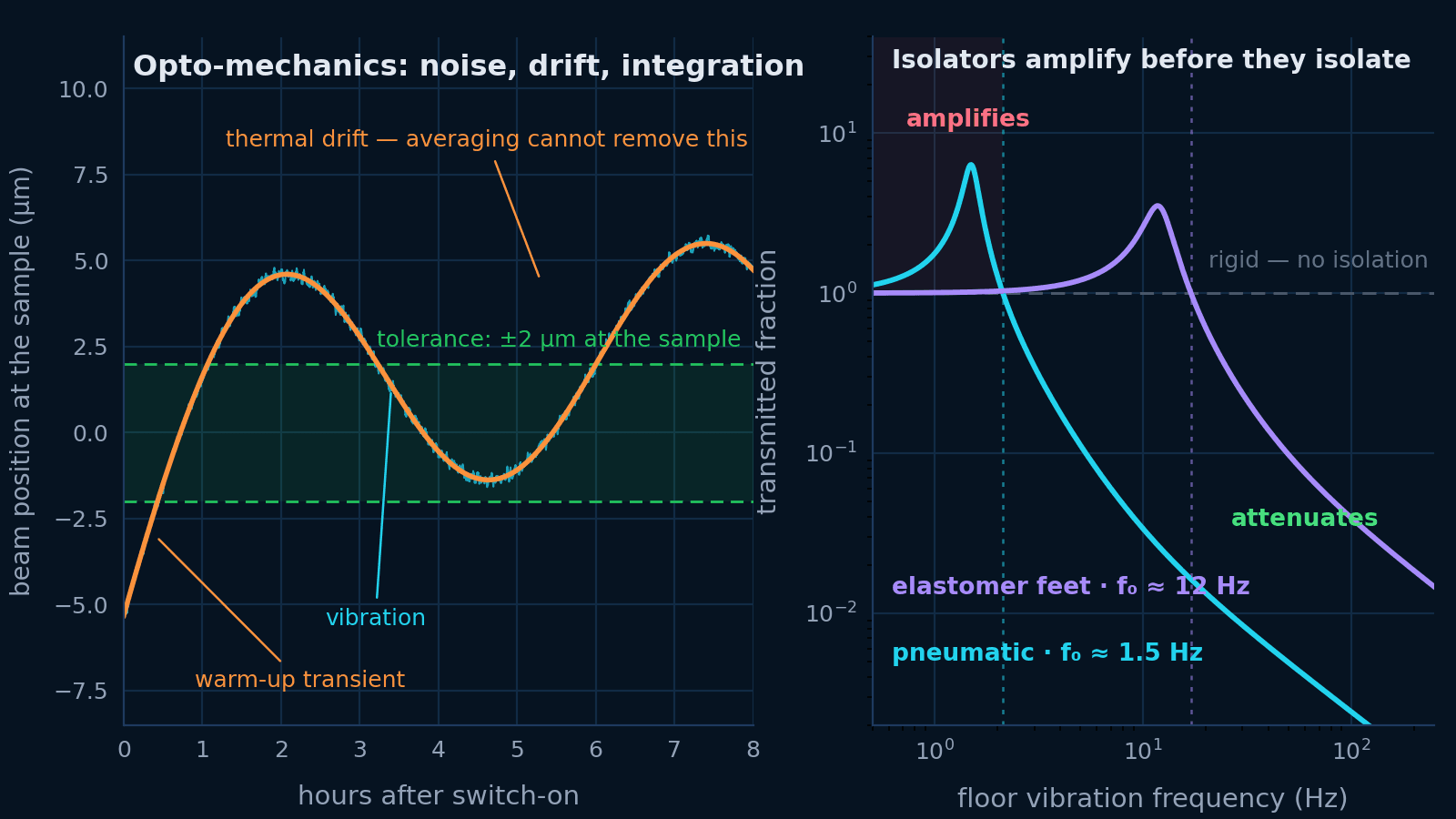
A passive isolator only attenuates above √2 times its own resonant frequency. Below that it transmits everything, and near resonance it amplifies — by a factor of several for a lightly damped mount. Elastomer feet resonating at 12 Hz make everything below about 17 Hz worse, which is precisely the band a building lives in.
Anything on the table is inside the isolation
A chiller line, a cooling fan, a shutter or a stage motor mounted on the tabletop injects force directly into the isolated mass. No amount of isolation from the floor helps. Decouple these at the source: flexible lines, separate supports, and where possible a shelf that is not the optical table.
3 · Thermal drift
The slow error that no averaging removes.
Vibration is symmetric about a mean, so integration helps. Drift is not: it accumulates, it correlates with everything else that changes slowly, and it is the reason a setup aligned at 5 pm is misaligned at 9 am.
The arithmetic
ΔL = α · L · ΔT
A 150 mm aluminium post through one kelvin moves about 3.5 µm. Two of them in opposite directions may cancel, or may not — differential expansion around the loop is what actually matters.
Aluminium
23.1 ppm/K
The default for posts and plates: light, cheap, and the largest thermal contributor in most rigs.
Stainless steel
≈ 16 ppm/K
Heavier and stiffer, with roughly a third less expansion. Often the pragmatic upgrade.
Invar 36
1.2 ppm/K
Twenty times more stable than aluminium. Reserve it for the few members that set the critical dimension.
Fused silica
0.55 ppm/K
For spacers and reference cavities, not for structure — it is brittle and awkward to mount.
Shorten the loop
A lower beam height is the cheapest thermal upgrade there is, and it improves bending stiffness at the same time.
Uniform, not cold
A stable temperature beats a low one. Gradients across the rig cause differential expansion, which is worse than uniform warming.
Let it settle
Most rigs need one to several hours after switch-on. Budget that into the working day rather than fighting the transient.
4 · Optical integration
Good components, badly connected, make a bad rig.
Integration is where most stability is won or lost — not in the specification of individual mounts. These six principles cost nothing and outperform most component upgrades.
Close the loop deliberately
Source, mounts, table, sample and detector form a mechanical loop. Anything that changes its shape moves the beam, so the shortest, stiffest, most thermally uniform loop wins — regardless of how good the individual components are.
Constrain exactly, never twice
A rigid body has six degrees of freedom and needs six constraints. Bolting a plate at four points on an imperfect surface over-constrains it, so tightening the last screw bends it and every temperature change re-bends it.
Keep beams low and posts short
Angular error scales with post length cubed for bending stiffness and linearly for thermal expansion. Dropping a beam height from 150 mm to 100 mm is usually the cheapest stability upgrade available.
Give every optic one job
A mount doing double duty — steering and translating, or holding two optics — couples adjustments together, so aligning one thing dealigns another and drift appears in more axes than you can measure.
Bolt to the table, always
Anything resting on its own weight will move: a knocked cable, a thermal cycle or a single pump stroke is enough. Free-standing components are for testing, not for a rig you intend to keep.
Design in the adjustment you need — and no more
Every adjustment axis is a potential drift axis. Where a degree of freedom is not needed after first alignment, lock it, pin it, or design it out.
Cage systems
Relative alignment is fixed by the rods, so a sub-assembly keeps its internal geometry when the rig moves. Excellent for collimators, filter stacks and compact imaging paths, and easy to enclose against air currents. Less good where the geometry must change often or where access is awkward.
Post-mounted optics
Free geometry and easy access, at the cost of every optic having its own independent path to the table. Keep posts short, use the largest diameter that fits, seat them fully in their holders, and standardise on one beam height across the whole rig so components can be swapped without realignment.
5 · Stability lab
Find out which term is actually costing you alignment.
Set the geometry, the materials, the floor and the tolerance. The lab combines pointing, thermal and vibration terms into one budget at the sample, names the dominant one, and shows whether your isolation is attenuating at your floor frequency or amplifying it.
Build the error budget
Rig stability lab
A focused beam across a bench: forgiving tolerances, and an error budget led by the longest lever arm in the path.
Error budget at the sample
total 7.02 µm · budget 5 µm
Total motion at the sample is 7.02 µm against a working budget of 5 µm, taken as a tenth of the 50 µm spot. The largest single term is mount angular drift at 6.93 µm — 3 mounts at 5 µrad each, amplified by a 400 mm lever arm.
Above √2 · f₀ = 2.1 Hz transmissibility falls as 1/f², so 300 nm of floor motion arrives as 4 nm. Note that this says nothing about acoustic noise or forces generated on the table itself — a fan or a pump on the tabletop is inside the isolation, not outside it.
Mounts are treated as independent, so their angular errors add in quadrature; a reflection doubles the angular deviation of the beam, and displacement at the sample is that angle times the lever arm. Thermal drift is free expansion of the post stack, α·L·ΔT, which ignores the differential expansion between the post, the table and the optic itself — real loops are usually worse. Vibration uses single-degree-of-freedom transmissibility with the f₀ and damping listed for each mount type; the working budget of one tenth of a spot diameter is a convention, not a rule, and interferometric measurements need a fraction of a wavelength instead.
6 · Diagnosing instability
The timescale tells you the cause.
Before changing hardware, log the motion. Almost every instability identifies itself by how fast it happens and what it correlates with — and the wrong diagnosis is expensive in a way the right one never is.
Milliseconds to seconds
Vibration or acoustics
Correlates with machinery, footsteps or speech. Tap-test the table and watch the ring-down; put an accelerometer on the floor and on the tabletop and compare.
Seconds to minutes
Air currents and index gradients
Comes and goes with HVAC cycles or an open door. Block the beam path with a tube: if the noise drops, it was never mechanical.
Tens of minutes to hours
Thermal drift
Monotonic or slowly cyclic, and correlated with room temperature or equipment warm-up. Log temperature alongside beam position — the correlation is usually unmistakable.
Days, or after an intervention
Creep and settling
Follows a change: a new mount, a retightened screw, a moved cable. Over-constrained joints and plastic parts under load relax for a long time.
Quadrant detector
Beam position at kilohertz rates — the standard instrument for pointing stability.
Camera on the beam
Slower, but shows shape and position together and needs no extra hardware.
Accelerometer
Distinguishes floor motion from tabletop motion, which is the only way to judge isolation.
Temperature logger
Cheap, and turns "it drifts" into a correlation you can act on.
7 · Tables + mounts
Buy the isolation your floor needs, not the isolation on the brochure.
Three table options covering pneumatic, damped and breadboard-scale support, plus the mounts and posts that carry the beam between them. Which is right depends on the floor spectrum and the tolerance — both of which the lab above will quantify for you.
Optical tables and breadboards
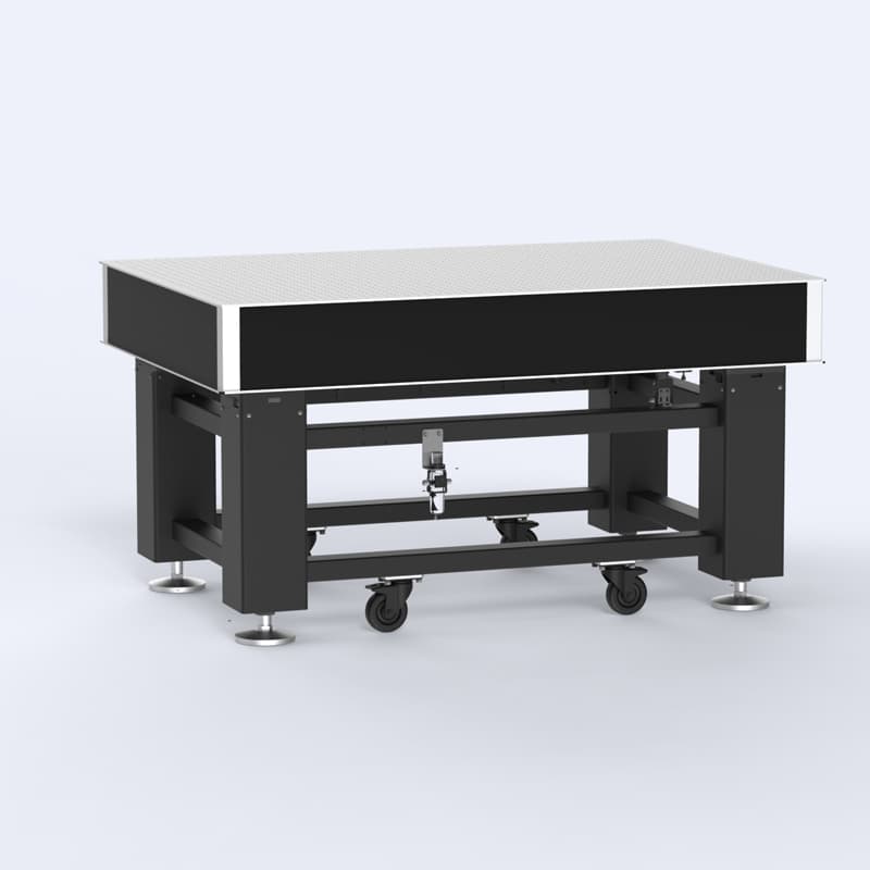
TPR15-09
A pneumatic table brings the isolation resonance down to a couple of hertz, which is the only way to reject the 5–20 Hz building motion that dominates most laboratory floors.
- Tabletop
- 1500 × 900 × 200 mm
- Tabletop weight
- 189 kg
- Isolation
- Pneumatic, self-levelling
- Foot area
- 160 × 160 mm
Qualify: Pneumatic support needs a clean, dry air supply and payload distributed so the isolators sit in their working range. Check load capacity against your actual equipment before choosing a size.
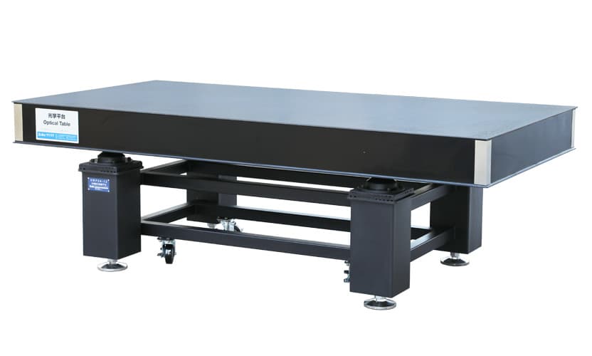
DRP12-12
A damped table without pneumatics suits quiet floors, sensitive-but-not-critical work, and rooms where compressed air is unavailable. The honeycomb top still moves the tabletop resonances up out of the band that matters.
- Tabletop
- 1200 × 1200 × 100 mm
- Tabletop weight
- 173 kg
- Isolation
- Damping legs
- Supported load
- 600 kg
Qualify: Damping legs do not isolate below their own resonance. If the floor has significant motion under about 20 Hz, this saves money in the wrong place.
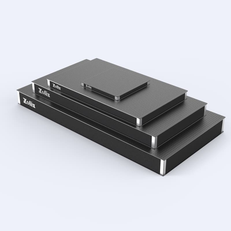
NTBK1212-100
Building a subsystem on its own breadboard keeps its internal alignment intact when the rig is rearranged, and lets a delicate assembly be aligned, enclosed and moved as one unit.
- Size
- 1200 × 1200 × 100 mm
- Construction
- Honeycomb core
- Use
- Sub-assembly or portable rig
- Thicknesses
- 50 / 100 / 150 / 200 / 300 mm
Qualify: A breadboard on a table adds a second mechanical loop and a new resonance. Bolt it down over its whole footprint rather than at the corners, and check it is not acting as a spring-mounted mass.
Mounts, posts and beam routing
Spend the mount budget where the lever arm is longest and the tolerance tightest. Everywhere else, a shorter post and a standard beam height contribute more to the error budget than a better mount would.
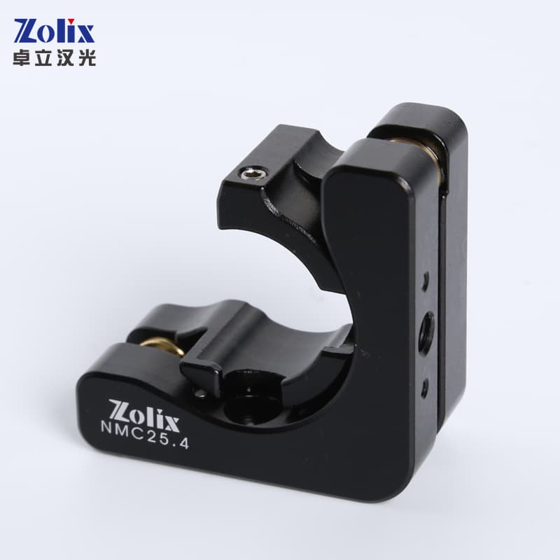
NMC25.4
Centre kinematic mount for Ø25–25.4 mm optics — two orthogonal angular adjustments and nothing else, which is exactly what a steering mirror should have.
- ±3° angular range
- Ø23 mm clear aperture
- 25 mm optical-axis height
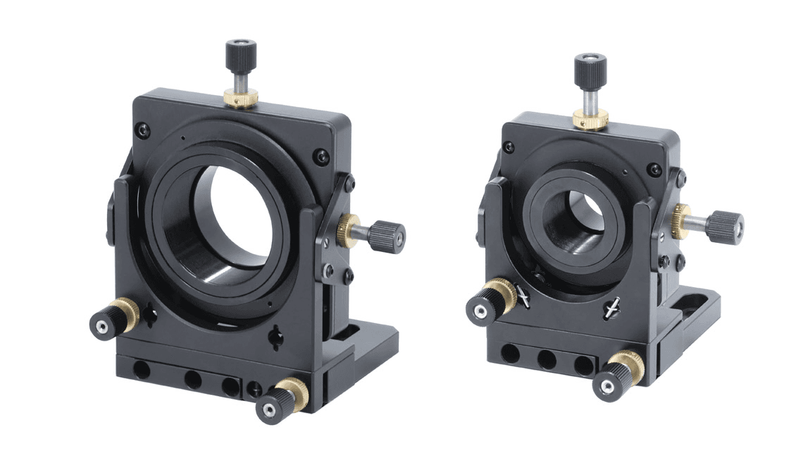
NMUM25.4
Five degrees of freedom in one body for the positions that genuinely need them — coupling into a fiber, or landing a beam on a small detector.
- ±2.5 mm X/Y
- 6 mm Z travel
- ±5° tip/tilt
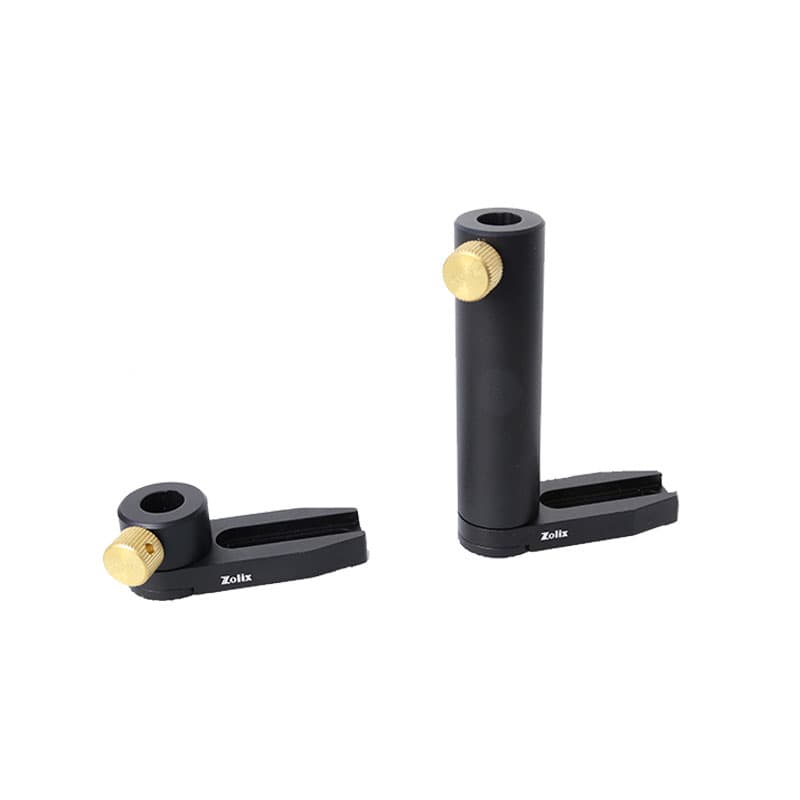
NPH50
Base-mounted holder for Ø12 mm posts. Choosing one beam height for the whole rig and keeping it low is worth more than any individual component upgrade.
- Ø12 mm post
- 50 mm overall height
- Base-mounted holder
Want the rig reviewed before you order it?
Bring the tolerance at the sample, a sketch of the beam path with distances, the floor and room conditions, and the equipment that has to sit on the table. That is enough to size the table, the isolation and the mounts as one system.
8 · Specification brief
Specify the rig, not the parts list.
These are the inputs that turn “it needs to be stable” into a set of components that can be quoted and, more importantly, verified once it is built.
Tolerance at the sample
The motion your measurement can absorb, in microns or wavelengths, and over what timescale it must hold.
Mechanical loop
Every component between source and detector, its material, and the length of the path that has to stay dimensionally stable.
Lever arms
Distance from each steering mount to the sample — the multiplier that turns microradians into microns.
Floor
Measured vibration amplitude and its dominant frequencies, before choosing between rigid, damped and pneumatic support.
Thermal environment
Room stability, air handling, equipment heat load, warm-up time, and whether an enclosure is possible.
On-table sources
Fans, pumps, chillers and shutters mounted on the table are inside the isolation and must be decoupled separately.
Access and adjustment
Which degrees of freedom are needed for first alignment, which are needed routinely, and which can be locked out.
Verification
How stability will actually be measured — position-sensitive detector, camera, interferometer, accelerometer — and against what threshold.
9 · Common questions
Short answers before the design review.
Do I need an optical table, or is a breadboard enough?+
It depends on the floor and the tolerance, not on the prestige of the experiment. A breadboard on a rigid bench is fine when the floor is quiet and the tolerance is tens of microns. You need a proper isolated table when floor motion in the 1–20 Hz band is comparable with your tolerance — which is typical of upper-floor labs, buildings with plant rooms, and anywhere near traffic. Measure the floor before deciding.
Why does my alignment drift overnight even though nothing moves?+
Almost always thermal. A 150 mm aluminium post changes length by about 3.5 µm per kelvin, and the room, the equipment and the building all cycle. The fix is shorter posts, a lower beam height, a more uniform thermal environment, or a lower-expansion material in the few members that set the critical dimension — not a stiffer mount.
Can vibration isolation make things worse?+
Yes, and this is the most common isolation mistake. Every passive isolator amplifies motion near its own resonance and only attenuates above about √2 times that frequency. Elastomer feet with a 12 Hz resonance amplify everything below roughly 17 Hz — which is exactly where building vibration lives. If the dominant floor frequency is low, you need a softer isolator, not simply an isolator.
How much does a microradian actually matter?+
It is entirely a question of lever arm: displacement equals angle times distance, and a reflection doubles the angle. One microradian of mirror tilt moves the beam by 2 µm at one metre, and by 6 µm at three metres. That is invisible for a millimetre-wide beam and catastrophic for a single-mode fiber core.
Should I use a cage system or post-mounted optics?+
Cage systems fix relative alignment mechanically, which is excellent for compact, repeatable sub-assemblies — collimators, filter stacks, small imaging paths — and they can be enclosed easily. Post-mounted optics give freer geometry and easier access, which suits long or reconfigurable paths. Many good rigs use cages for the fixed subsystems and posts for everything between them.
How do I tell vibration from drift?+
By timescale. Vibration lives in milliseconds to seconds and correlates with machinery or footsteps. Air currents act over seconds to minutes and disappear when you enclose the beam. Thermal drift runs over tens of minutes to hours and correlates with temperature. Log beam position and room temperature together for a day — the diagnosis is usually obvious from the trace.
Is it worth over-specifying mounts?+
Rarely. Mount quality matters most for the few optics with the longest lever arms and the tightest tolerances. Elsewhere the money is better spent on a shorter beam height, an enclosure, decoupling a pump, or fixing the thermal environment — all of which usually contribute more to the error budget than the difference between a good mount and an excellent one.
Continue designing
Put the rig under a real experiment.
A note on the numbers
Thermal expansion coefficients are standard room-temperature values and vary with alloy and temper — aluminium alloys span roughly 21–24 ppm/K and stainless grades 10–17 ppm/K, so treat the figures here as design estimates and use the value for your actual material where it matters. Isolator behaviour is modelled as a single degree of freedom, which captures the resonance and the 1/f² roll-off but not tabletop bending modes, rocking modes, or the internal damping of a honeycomb top. For anything demanding, measure: a floor vibration survey costs a fraction of the table it will help you specify correctly.