How to Choose a Precision Positioning Stage:Linear, Piezo, or Cryogenic Piezo?
Stop selecting motion hardware by the smallest resolution number on a datasheet. Match travel, resolution, payload, settling time, vacuum grade, temperature, and magnetic field requirements to the correct positioning architecture.
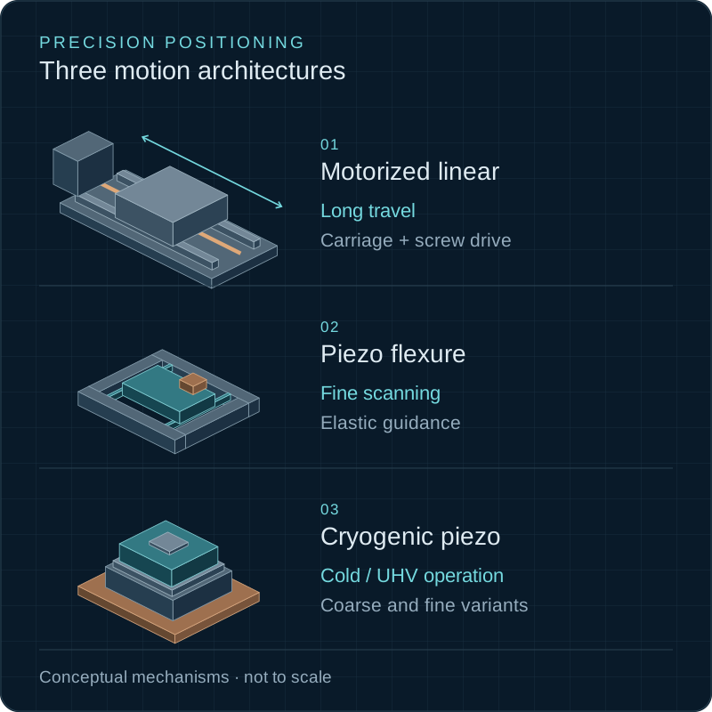
From nano flexure stroke to meter ball-screw travel
Sub-nanometer capacitive feedback to closed-loop linear scale
Tested for dilution refrigerators, cryostats & ambient labs
Zero outgassing materials, UHV connectors & non-magnetic Ti
1. Begin with the Motion Requirement
Selecting motion hardware begins by evaluating the core physics of your measurement. Datasheets often emphasize resolution, but resolution without accuracy, stiffness, and thermal stability is meaningless in real optical setups.
The smallest position increment detectable by the position sensor or motor step. It is a theoretical floor, NOT a guarantee of true physical carriage displacement.
The ability of a stage to return to an identical commanded position when approached repeatedly from the same (unidirectional) or opposite (bidirectional) directions.
The maximum difference between true physical displacement and commanded position over the full travel range, verified by laser interferometry.
The 14 Core Motion Parameters:
Total displacement range needed (e.g. 100 µm vs 100 mm).
Smallest repeatable physical step the stage must reliably execute.
Unidirectional vs. bidirectional error during direction reversals.
Total error over full stroke relative to absolute spatial coordinate.
Encoder capability (capacitive, optical glass scale, or resistive).
Maximum scanning rate and dynamic velocity stability.
Duration required for post-step mechanical ringing to dampen below noise floor.
Static payload mass and dynamic forces applied during acceleration.
Linear (X, Y, Z), Rotary (θ), Goniometric (tilt), or 6-DOF hexapod.
Horizontal, vertical lift (Z axis), or inverted overhead mounting.
Continuous scanning vs. low duty step-and-hold operation.
Ambient room temp, High Vacuum, UHV, Cryogenic, or High Magnetic Field.
Space available inside cryostat bore, microscope turret, or cage system.
Closed-loop PID controller, analog drive, LabVIEW / Python SDK.
2. Motorized Linear Stages
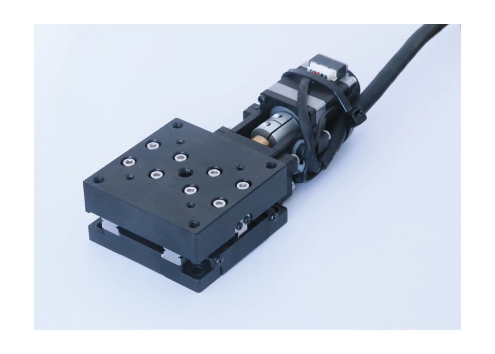
Motorized linear translation stages represent the backbone of automated laboratory motion. They combine electric actuators (stepper or brushless servo motors) or direct-drive linear motors with precision mechanics to translate rotary motion into linear displacement over centimetres to metres.
- • Ball Screws: High efficiency, zero-backlash preloaded screws (Zolix LAK/KA series).
- • Direct-Drive Linear Motors: Ironless core for scanning speeds >500 mm/s.
- • Crossed-Roller Guides: High moment stiffness & <5 µrad straightness.
- • Linear-Ball Bearings: Smooth motion over long strokes at low cost.
- • Closed-Loop Encoder: Linear glass scales (50 nm / 10 nm) cancel screw errors.
- • Backlash Cancellation: Optical scale feedback cancels mechanical lead-screw play.
- • Vertical Lift Derating: Motor brakes & wedge-lift stages (CZF / CXZ) for heavy Z loads.
- • Multi-Axis Stacking: High pitch/yaw stiffness prevents cantilever error.
3. Ambient Piezo Stages
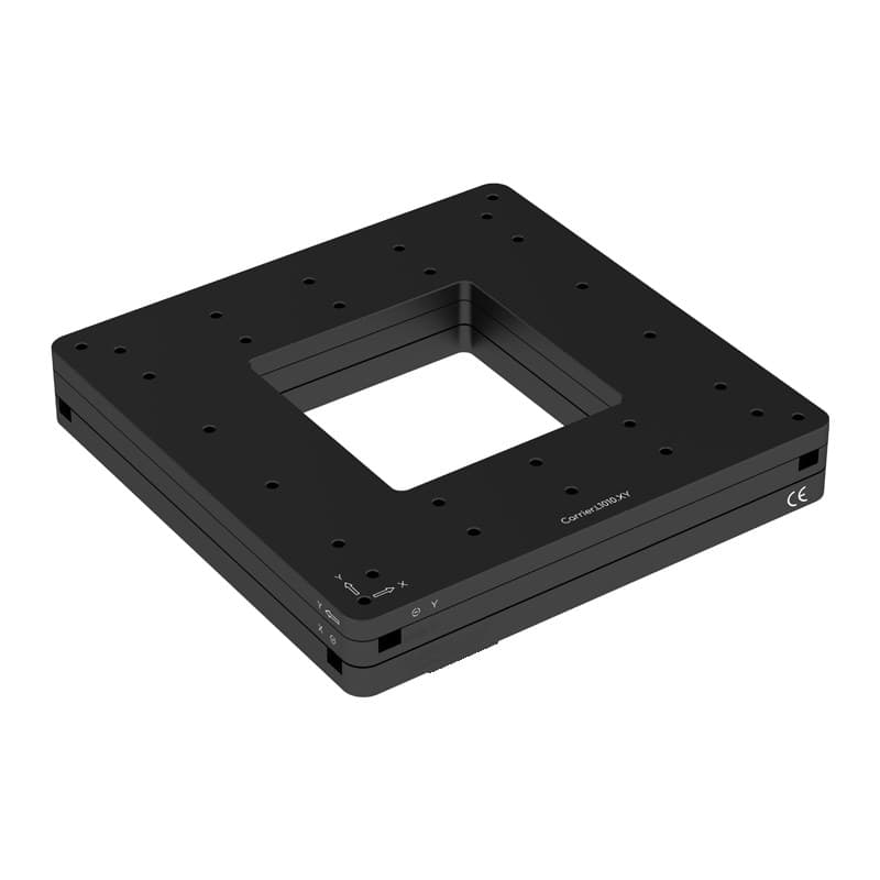
Piezoelectric stages generate motion through the reverse piezoelectric effect: applying a voltage across a ferroelectric ceramic (PZT) produces physical dimensional expansion. Because piezo expansion is friction-free, piezo stages deliver sub-nanometre resolution and millisecond dynamic response.
Elastic flexure hinges provide friction-free, sub-nm motion over 10 µm to 500 µm range (S100/S300 series).
Saw-tooth voltage pulses step a runner, combining multi-mm stroke with nm fine step (LS35 / L030 series).
Capacitive or strain-gauge sensors measure actual motion, eliminating 10–15% hysteresis and creep.
Adding payload mass lowers the first mechanical resonant frequency according to:
Closed-loop controllers utilize digital notch filters to prevent resonance oscillation during fast raster scanning.
4. Cryogenic and UHV Piezo Stages
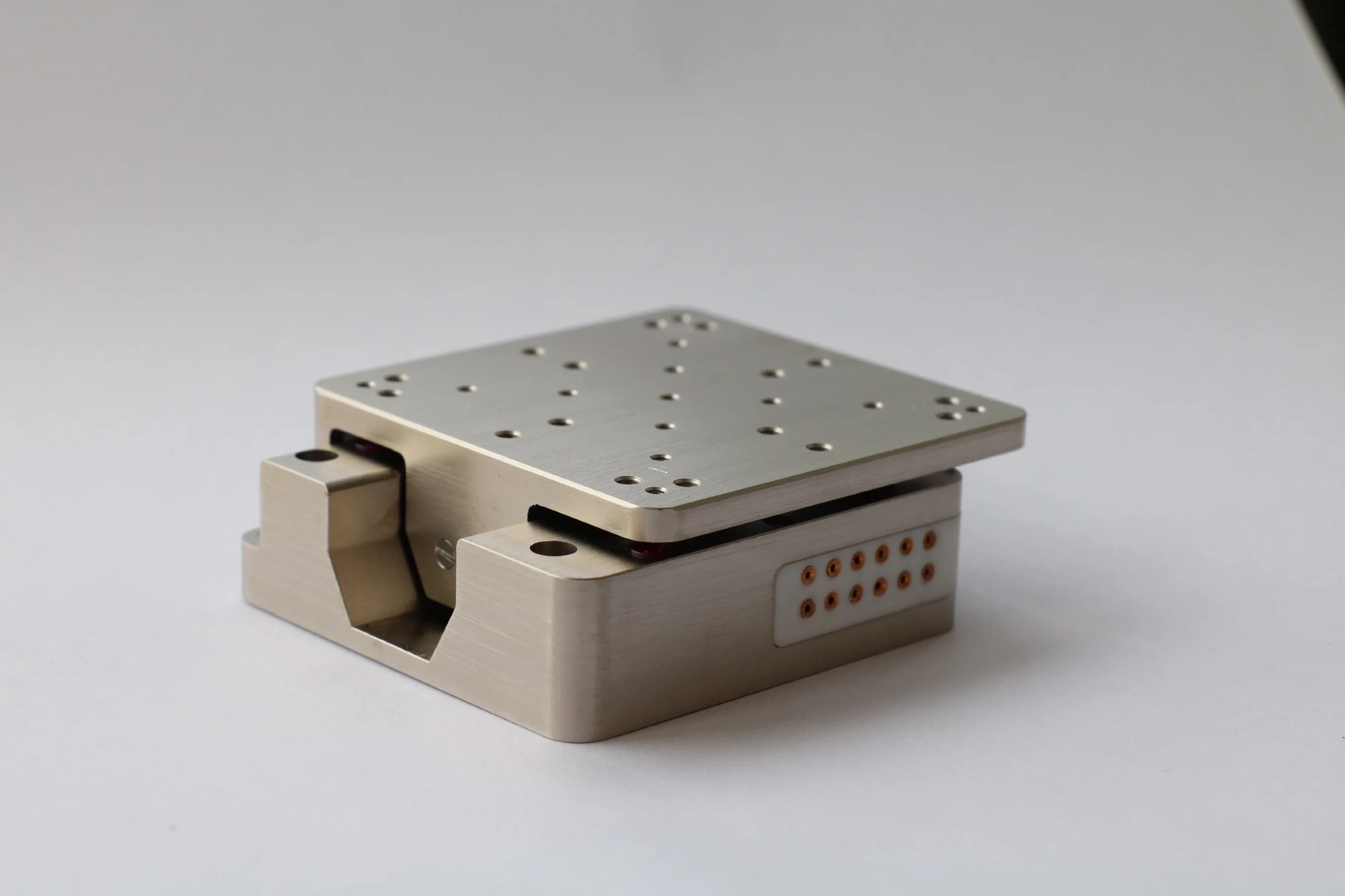
Inside dilution refrigerators (10 mK), high-field superconducting magnets (>35 T), or ultra-high vacuum chambers ($2\times 10^-11$ mbar), standard electric motors fail due to organic grease freezing, outgassing, and magnetic field quenching. Pure titanium stick-slip piezo positioners operate reliably from 10 mK to 400 K.
Physics of Low-Temperature Piezo Positioning
5. Direct Comparison Table
Compare performance, holding behavior, heat dissipation, and environmental compatibility across all four primary stage technologies based on verified catalog data.
| Parameter / Specification | Motorized Linear Stage | Ambient Piezo Stage | Cryogenic Piezo Stage | Manual Stage |
|---|---|---|---|---|
| Typical Travel Regime | 20 mm to >500 mm | 10 µm to 100 mm (stick-slip) | 3 mm to 200 mm (stick-slip) | 13 mm to 50 mm |
| Fine Positioning Floor | 0.05 µm to 0.5 µm | Sub-nanometre (<0.1 nm) | Sub-nanometre (<0.1 nm) | 0.5 µm to 1 µm |
| Maximum Speed | 10 mm/s to 500 mm/s | Up to 100 mm/s (scanning) | 1 mm/s to 5 mm/s (stick-slip) | Manual adjustment |
| Maximum Payload | 5 kg to >50 kg | 100 g to 5 kg | 50 g to 2.5 kg | 1 kg to 10 kg |
| Closed-Loop Feedback | Linear optical scale encoder | Capacitive / strain-gauge | Resistive / Capacitive / Optical | None (Micrometer scale) |
| Holding Behavior | Motor current / Mechanical brake | Continuous voltage (or off) | Self-locking friction (zero heat) | Mechanical position clamp |
| Heat Generation | Moderate to High during motion | Low static; high at high freq | Zero heat when held stationary | Zero electrical heat |
| Vacuum Compatibility | Standard Air; HV options | Standard Air; HV options | Down to 2×10⁻¹¹ mbar (UHV) | Air & UHV variants available |
| Cryogenic Compatibility | Not compatible (<250 K failure) | Not compatible (<250 K failure) | 30 mK to 400 K (.ULT option) | Requires special dry lubricants |
| Magnetic Field Rating | Non-compatible (iron motor) | Non-magnetic option (.NM) | Pure Titanium (up to 35 T) | Non-magnetic stainless/bronze |
| Footprint Envelope | Large (60 mm to 300+ mm) | Compact to Moderate | Ultra-compact (16x16 mm base) | Compact to Moderate |
| Controller Requirements | Multi-axis stepper/servo driver | Low-noise HV piezo amplifier | Cryo stick-slip + HV driver | None required |
| System Complexity | Moderate | Moderate to High | High (thermal & cabling) | Low |
| Best Application Regime | Automated long-range alignment | Nanometer scanning & autofocus | Cryostat & UHV transport physics | Initial alignment setups |
6. Coarse / Fine Positioning Systems (Stacked Hybrids)
When an instrument demands both multi-centimetre travel and sub-nanometre focus or active drift stabilization, mount a fine flexure piezo stage onto a coarse motorized linear stage.
Navigates across large sample areas with ±0.5 µm accuracy.
Executes fast sub-nm raster scans and active jitter locks.
Key Design Considerations for Hybrid Systems:
6 Concrete Application Architecture Examples:
Long-range slide scanning with millisecond autofocus stabilization.
Coarse optical fiber positioning with sub-nm power coupling optimization.
Coarse path-length matching + 100 Hz phase-lock stabilization.
Dilution refrigerator transport physics with low-temperature capacitive feedback.
Coarse spectral band selection + high-resolution fine wavelength tuning.
Sample chamber positioning with nanonewton trap calibration.
7. Motion Specifications Decoded
Avoid costly hardware specifying mistakes. Review the 8 most frequent datasheet misinterpretations before selecting motion stages.
A 10 nm encoder reports 10 nm counts, but lead-screw non-linearity can cause 2 µm absolute error.
Unidirectional repeatability looks great, but mechanical backlash degrades reverse approach 5x.
A piezo scanner claims 1000 Hz resonance, but adding a 500 g sample drops resonance to 200 Hz.
Stages rated for 10 kg horizontal load often drop to 2 kg vertical load due to gravity.
Stiff motor or piezo cables attached to carriage generate lateral forces that tilt delicate flexures.
Piezos lose 70% stroke at 4.2 K, and standard lubricants freeze solid.
Combining three light stages creates a wobbly cantilever with excessive Abbe error.
Open-loop piezos exhibit 10–15% hysteresis and continuous creep over minutes.
Stage Architecture Lab
Select your experimental constraints to determine the exact motion architecture, controller strategy, and verified product series.
1. Define Motion Requirements
2. Recommended Positioning Architecture
Ambient Flexure / Piezoelectric Nanopositioner
Sub-nanometre resolution, millisecond response times, or active high-frequency stabilization require friction-free flexure-guided piezo actuators. Unlike mechanical screw drives, flexure stages eliminate friction, backlash, and mechanical wear, providing continuous motion with infinite sub-nanometer resolution.
Key Specifications to Verify
- •Closed-loop sensor resolution: capacitive or optical strain-gauge feedback for hysteresis correction.
- •Resonant frequency: unloaded vs. loaded first mechanical resonance dictates dynamic scanning speed.
- •Drive voltage & amplifier bandwidth: ensure controller supports peak current for high-frequency scanning.
- •Thermal drift: active heat dissipation if operated continuously at high drive amplitude.
Limitations & Gotchas
- •Short travel range (typically 10 µm to 500 µm for flexures; up to 20–40 mm for stick-slip piezos).
- •Sensitivity to lateral overloads or shock forces on delicate flexure hinges.
9. Worked Decision Examples
Real laboratory case studies showing how to specify stage architectures, position feedback, and controllers for specific experimental setups.
10. Motion System Diagnostic Matrix
| Observed Problem | Probable Cause | Diagnostic Check | Corrective Action |
|---|---|---|---|
| Position drifts after settling | Open-loop piezo creep or thermal expansion from motor heating | Monitor position sensor trace over 10 minutes | Enable closed-loop PID control or reduce motor holding current |
| Different positions when approaching from +/- directions | Mechanical backlash in lead screw or bearing play | Measure reversal error using a dial indicator | Switch to preloaded ball screws or closed-loop linear scale feedback |
| High-frequency oscillation in closed loop | PID loop gains too aggressive or payload mass lowered resonant frequency | Perform step-response test & inspect noise spectrum | Lower P gain, increase D filtering, or add digital notch filter |
| Poor positioning repeatability under heavy load | Carriage moment load exceeds guideway rating, causing binding | Measure pitch/yaw angle during motion under load | Upgrade to crossed-roller stage (CXP series) or add counterweights |
| Excessive vertical axis drift when powered off | Gravity pulling carriage down against unbraked motor | Observe Z position when motor power is disengaged | Add motor brake, counterbalance spring, or use wedge-lift stage |
| Piezo travel saturates near end of range | Coarse stage initial position shifted piezo away from 50% midpoint | Check piezo controller drive voltage readout (0–100 V) | Re-center piezo using coarse motorized stage step before fine scan |
| Cryostat base temperature rises during motion | Stick-slip piezo stepping dissipating electrical heat into cold plate | Monitor cryostat temp sensor during continuous stepping | Reduce stepping frequency, lower voltage, or power down piezo after step |
| High position noise induced by cables | Stiff motor or piezo cables transmitting ambient room vibrations | Gently flex cables while observing position sensor readout | Anchor cables to optical breadboard with strain relief before stage |
| Severe mechanical resonance after stacking stages | Combined stack height lowered first mechanical bending mode | Tap upper stage and record ring-down frequency on oscilloscope | Increase stage body width, use stiff titanium plates, or lower stack height |
| Piezo stage fails to move at cryogenic temperature | Stick-slip drive voltage insufficient due to diminished d33 coefficient at 4 K | Check drive amplitude setting on cryogenic controller | Increase stick-slip drive voltage amplitude (e.g. 40 V to 60 V) as specified for 4 K operation |
11. Verified Product Ecosystem Integration
Browse verified stage families with direct links to catalog pages, specification tables, and custom engineering inquiry forms.
Motorized Stages & Motion Control →
Submicron linear (LAK, KA, CXP), vertical elevation (CZF), rotation (TBRU), goniometer (GONX), and 6-DOF hexapods. Preloaded ball screws and linear glass scale encoders.
Ambient Piezo Stages →
Sub-nanometer flexure scanners (S100, S300), objective autofocus carriers (Carrier.OB), lab linear piezo motors (LS35, LS65), and parallel 3-DOF/6-DOF piezo platforms.
Cryogenic Piezo Stages →
Pure titanium positioners rated from 30 mK to 400 K and vacuum down to 2×10⁻¹¹ mbar. Stick-slip linear (Linear16/25/35), rotators, and closed-loop Ultra capacitive scanners.
Manual Stages & Positioners →
Ultra-high precision crossed-roller linear stages (NFP), stainless steel and aluminum series (SK, AK), vertical positioners (SKV), rotary stages (SKR), and multi-axis combined stacks.
12. Frequently Asked Questions
What is the difference between a linear stage and a piezo stage?↓
Can a piezo stage replace a motorized linear stage?↓
When should I combine coarse and fine stages?↓
Is encoder resolution the same as positioning accuracy?↓
Do I need closed-loop feedback?↓
Why does a piezo stage creep?↓
Can an ambient piezo stage operate in vacuum?↓
Why does piezo travel change at cryogenic temperature?↓
What stage should I use inside a high magnetic field?↓
How does payload affect resolution and settling time?↓
Which stage is best for vertical positioning?↓
How should stacked stages be controlled?↓
Further Engineering Reading
Related Precision Motion & Rig Guides
 Opto-mechanics
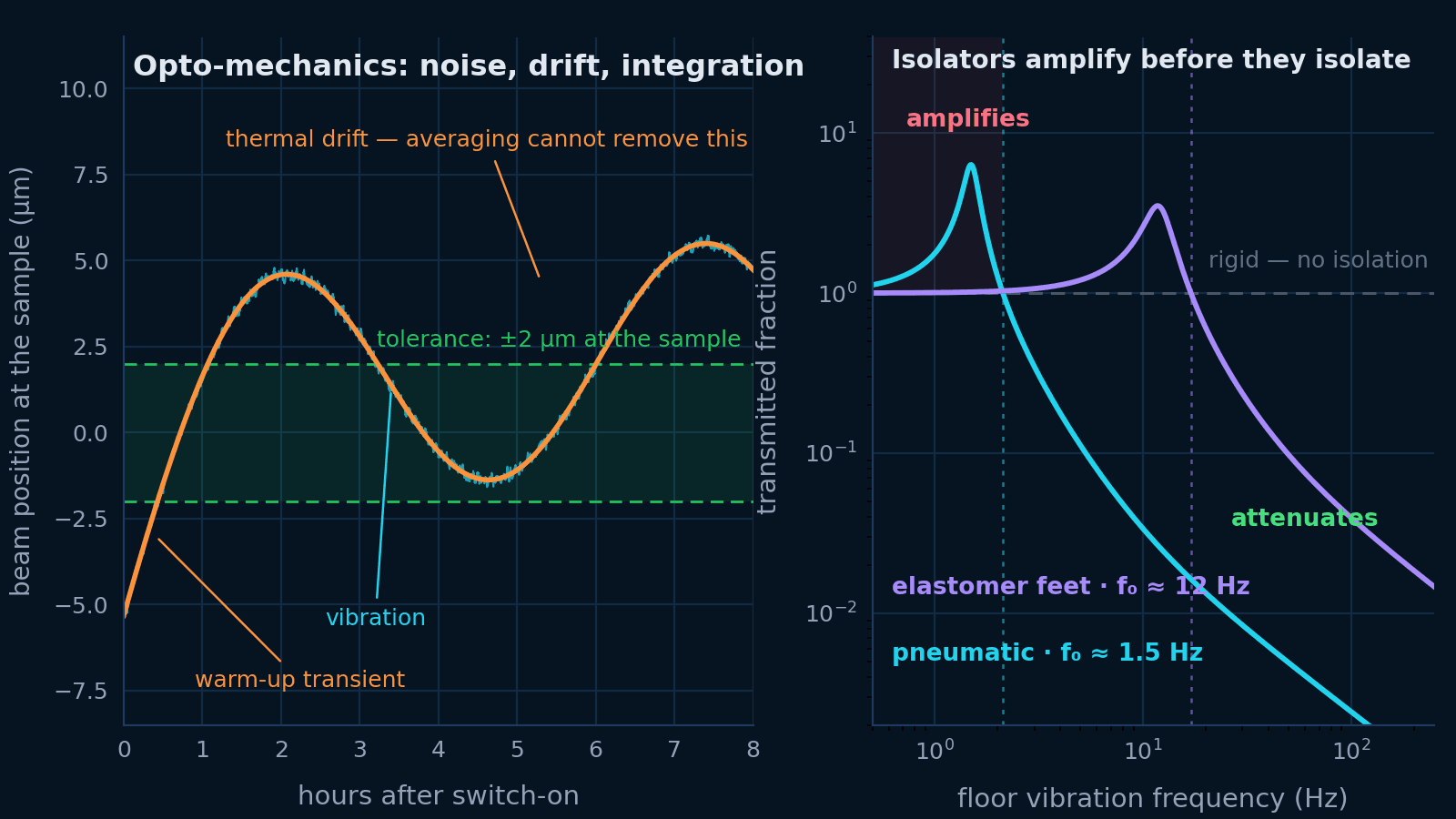
Building a stable opto-mechanical rig
Vibration, thermal drift and mechanical integration are one problem. Budget the motion at the sample, then specify the table, the isolation, the mounts and the beam height that budget asks for.
Open guide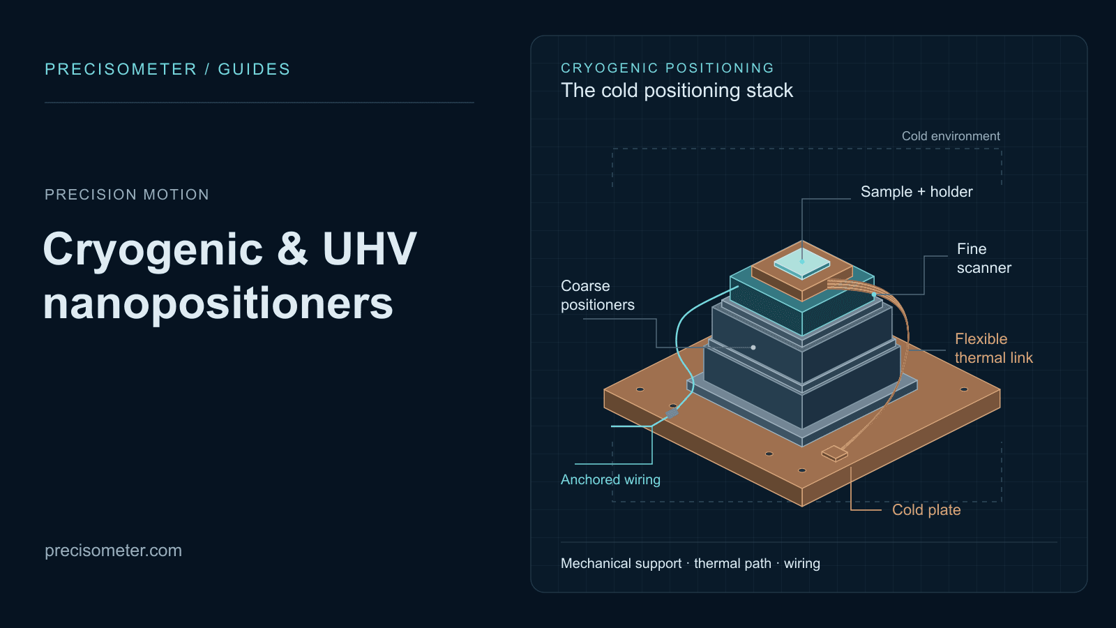 Precision motion
Selecting nanopositioners for cryogenic and UHV systems
Translate temperature, pressure, travel, payload, feedback, and motion requirements into a defensible cryogenic-stage shortlist.
Open guide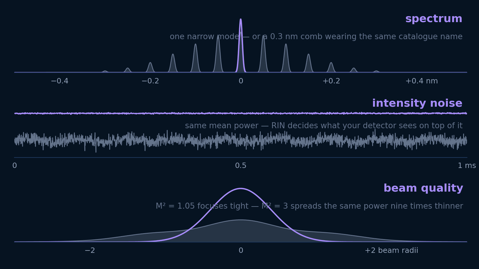 Photonics
Laser specifications decoded
Linewidth, spectral width, RIN, M², and coherence length answer five different questions. Translate each into the units your experiment is designed in — and learn which ones not to pay for.
Open guide