Microscope sample stage
20″ pitch → 5.8 µmSpecimen 60 mm above the guide
Larger than the resolution of most objectives, and it appears as a field shift that tracks stage position — easily mistaken for sample drift.
Precision engineering · 15 min
Angular error multiplied by offset. It is the largest geometric error in most precision machines, it is first order rather than second, and it appears on no datasheet — because half of the product belongs to you, not to the supplier.
e = θ · d
One arcsecond contributes 4.85 nm per millimetre of offset.
The principle
Ernst Abbe’s statement is simple: the measuring scale must lie collinear with the dimension being measured. Put the scale beside the thing you are measuring rather than in line with it, and any angular deviation of the mechanism turns into a linear error that scales with how far apart they are.
In a positioning system this shows up as follows. A stage carriage does not merely translate — it also pitches, yaws and rolls by small amounts as it travels, because no guideway is perfect. If your work point sits directly on the guide axis, those rotations produce no translation there. If it sits a distance d away, they produce a displacement of approximately θ·d, and your carefully specified stage puts the tool somewhere other than where the encoder says.
What makes this worth a page of its own is the first-order dependence. Most alignment errors in optics and metrology are second order — they go as the square of a small angle, which is why they can usually be ignored. Abbe error is linear in both the angle and the offset, so it survives at magnitudes where everything else has vanished.
Calculator
Pitch, yaw and roll from the datasheet; the offset from your own drawing. Every angle-times-offset product is shown separately, because the useful answer is not the total — it is which offset to engineer away.
Enter the pitch, yaw and roll from the datasheet, then where your work point actually sits relative to the guide. Every term is shown separately, because the useful output is not the total — it is knowing which offset to engineer away.
Angular error of the guide
Typical over full travel: 60″ for a dovetail, 20″ for a recirculating ball guide, 10″ for crossed roller, under 5″ for a precision or air-bearing guide.
Work point offset from the guide
Measured from the centre of the guideway to the point you actually care about — the focus, the probe tip, the tool, the interferometer beam.
Abbe error at the work point
8.23 µm
Vector magnitude with the terms as signed above. Worst case, if every angular deviation happens to add rather than partially cancel: 11.64 µm.
Along travel (X)
5.82 µm
Transverse (Y)
-5.82 µm
Vertical (Z)
0 µm
What to do about it
The dominant term is pitch × height at 5.82 µm, which is 50 % of the worst-case budget. Halving that one offset halves that term — and unlike buying a better guide, moving the work point is usually free. Improving the guide is the second lever; note that going from 20″ to 5″ buys you a factor of four, while reducing the offset from 60 mm to zero buys you all of it.
The whole calculation
δ = θ × r ⟹ δₓ = θ_pitch·d_z − θ_yaw·d_y
One arcsecond is 4.848 microradians, so it contributes 4.85 nm of error per millimetre of offset. That single conversion is worth memorising: at a 100 mm offset, every arcsecond of guide error costs you very close to half a micrometre.
Small-angle rigid-body model. Real guides deviate differently at every position along travel, so the datasheet figure is a peak or a band rather than a constant — and the angular error at the point you actually work may not be the worst-case value quoted. Straightness and flatness of travel add separately and are not Abbe terms. Elastic deformation of the carriage under load adds to the angular error and is not included here.
A common confusion
Both come from a misalignment between the measurement axis and the axis of motion, and they are routinely conflated. They differ by orders of magnitude, and only one of them is worth your attention.
| Error | Formula | Order | Cause | At 1 mrad |
|---|---|---|---|---|
| Abbe error | e = θ · d | First order | Angular error acting through an offset | 1 mrad at 100 mm offset → 100 µm |
| Cosine error | e = L · (1 − cos θ) ≈ L·θ²/2 | Second order | Measurement axis tilted relative to the motion axis, with no offset | 1 mrad over 100 mm → 0.05 µm |
The two rows differ by a factor of two thousand at the same angle. That is the whole reason Abbe wrote it down: second-order alignment errors forgive you, and first-order ones do not. If you take one thing from this page, take the habit of asking “what is my offset?” before asking what the stage costs.
Worked examples
Specimen 60 mm above the guide
Larger than the resolution of most objectives, and it appears as a field shift that tracks stage position — easily mistaken for sample drift.
120 mm lateral, 40 mm high
Reaching sideways off the carriage engages yaw and roll together. The most common way a machine that passed acceptance fails on the line.
160 mm of stack plus 50 mm fixture
Each axis acts through its own arm and they add. The bottom stage dominates because it works through the full height of everything above it.
Zero offset by construction
The Abbe principle satisfied exactly. This is not a coincidence of good engineering — it is the reason the layout is chosen.
Interactive
In a tower each stage acts through its own Abbe arm, and the bottom stage works through the full height of everything above it. The design rule that falls out is not the one most people follow.
In a stacked XYZ tower each axis carries a different Abbe arm. The bottom stage acts through the full height of everything above it — which inverts the usual instinct about where to spend money.
Bottom (X)
Middle (Y)
Top (Z)
Fixture, chuck and sample height above the top stage’s guide plane.
A six-axis platform has one guide plane rather than three stacked ones.
Total Abbe error of the stack
44.12 µm
Stack is 160 mm tall; the work point sits 210 mm above the table.
The design rule
The bottom (x) stage contributes 20.36 µm — 46 % of the total — because it works through a 210 mm arm. The instinct is to spend money on the fine axis at the top; the arithmetic says spend it at the bottom, where the lever is longest. Halving the angular error of the bottom stage buys you far more than halving it on the top.
A parallel platform at the same 20″ gives 10.67 µm — 4.1× better. It collapses three stacked guide planes into one, so there is a single Abbe arm instead of three that add. That, rather than the axis count, is the real argument for parallel kinematics — and it is also why reducing stage heights helps even when you keep the tower.
Contributions are summed linearly, which is the worst case; in practice the three angular deviations are independent and may partially cancel at any given position. Stage heights are the distance from each stage’s mounting face to the next guide plane, which is not always the overall height on the datasheet. Elastic deflection under load, and the straightness of each axis, add separately.
The fixes
The Abbe principle stated as an instruction rather than a warning. If the offset is zero, the angular error contributes nothing at all — no matter how poor the guide is. This is why a laser interferometer is aligned along the axis of motion rather than beside it.
Halving the height of a fixture halves that error term outright. A low-profile stage, a shallower chuck or a shorter tool holder often buys more accuracy than the next grade of guideway, and costs nothing per unit.
Crossed roller instead of recirculating ball, or air bearing instead of either. Going from 20 arcsec to 5 buys a factor of four — real, but bounded, and you pay for it on every axis in the machine.
Put the metrology where the work is, so the loop encloses the angular error rather than sitting beside it. This is what makes an interferometric axis genuinely accurate, and it is the only approach that also catches thermal drift in the structure.
Measure pitch and yaw against position, store the map, correct in software. It works only for the repeatable part of the error, needs re-doing as the machine wears, and does nothing about load-induced deflection that varies with your payload.
Note the ordering. The two cheapest fixes are geometric and the expensive ones are not — yet the usual response to an accuracy problem is to buy a better stage, which is third on this list. Work out the offset before you work out the budget.
Hardware that helps
Each of these attacks one specific term in the calculation above, rather than promising accuracy in general.
Crossed rollers make line contact rather than point contact, which raises moment stiffness and lowers the pitch and yaw deviation over travel. Both halves matter here: less baseline angular error, and less additional tilt when your payload sits off-centre. This is fix number three, and on a cantilevered payload it is often the only one available.
Fix number two in hardware form. A low-profile stage puts the guide plane closer to your optic, and since the error is linear in that distance, height saved is error saved — with no recurring cost and no compromise anywhere else in the machine.
A parallel-kinematic platform collapses a stacked tower into a single guide plane, so there is one Abbe arm rather than three that add. The controller also offers a virtual pivot, which lets you place the centre of rotation at your work point — which is the Abbe principle applied to rotation rather than translation.
A goniometer rotates about a centre above its own body, so you can place that centre on your sample rather than inside the mechanism. Same principle as the virtual pivot: if the axis of rotation passes through the work point, the offset is zero and the angular motion stops producing translation you did not ask for.
Common questions
Abbe error is the linear positioning error produced when an angular error acts through an offset. If the guideway pitches by an angle θ and your work point sits a distance d away from the guide, the work point moves by approximately θ·d even though the carriage went exactly where it was told. It is named after Ernst Abbe, who stated in 1890 that the measuring scale must lie collinear with the dimension being measured. Where that condition is not met, guide angular error couples directly into your measurement, and it does so in first order — proportional to the offset, not to its square.
For a single angular deviation the calculation is e = θ · d, with θ in radians and d the perpendicular offset from the guide to the work point. Because one arcsecond is 4.848 microradians, a convenient shortcut is that each arcsecond of angular error contributes 4.85 nanometres per millimetre of offset — so 20 arcseconds at a 100 mm offset gives about 9.7 µm. In three dimensions the general form is the cross product δ = θ × r, where θ is the vector of roll, pitch and yaw and r is the offset vector. That expands to an error along the travel direction of pitch times height minus yaw times lateral offset, with corresponding expressions for the other two axes.
They are different failures of the same alignment. Cosine error arises when the measurement axis is tilted relative to the axis of motion but passes through it: the measured length is short by L·(1−cos θ), which is second order and approximately L·θ²/2. Abbe error arises when the measurement axis is parallel to the motion but offset from it: the error is θ·d, which is first order. The practical consequence is a large difference in size. At one milliradian, cosine error over 100 mm of travel is about 0.05 µm; Abbe error at a 100 mm offset is 100 µm — two thousand times larger. Cosine error is usually negligible. Abbe error usually is not.
Because the manufacturer does not know where your work point is. A datasheet can give you positioning accuracy and repeatability measured at the platform, and it can give you pitch, yaw and roll deviation over travel — and good ones do. What it cannot give you is the offset, because that is a property of your fixture, your optic and your tool. Abbe error is the product of a number the supplier knows and a number only you know, which is precisely why it is so often left out of an error budget entirely.
It depends entirely on where your offset is. For error along the direction of travel, pitch acts through the height of the work point above the guide, and yaw acts through the lateral offset. If your payload sits directly above the carriage, pitch dominates and yaw contributes almost nothing. If it reaches out sideways, yaw and roll both engage. Roll only produces error when there is a lateral or vertical offset, which is why it is often ignored in a simple analysis and then turns out to matter on a cantilevered tool. Work out your offset vector first, and the relevant angle follows from it.
Only if the encoder scale is collinear with your work point, which it almost never is. A linear encoder mounted on the platform corrects screw pitch error, backlash and thermal expansion of the drive train, because those all lie inside the loop it closes. Angular error of the guideway is outside that loop: the encoder reads the correct position of the scale, while the work point at some offset from the scale has moved somewhere else. This is why adding an expensive encoder to a stage with mediocre guideways often disappoints — it fixes the terms it can see and leaves the dominant one untouched.
The repeatable part of it can. Measure pitch and yaw as a function of position with an autocollimator or an interferometer, store the map, and have the controller correct for it — this is standard practice on coordinate measuring machines and on lithography stages. Three limits apply. It only corrects what repeats, so bearing noise and hysteresis survive. It needs redoing as the machine wears or is re-assembled. And it cannot anticipate load-induced deflection, so a map taken with one payload is wrong for another. Compensation is a genuine tool and a poor substitute for geometry.
Start at the bottom, which is counterintuitive. Each stage in a tower acts through its own Abbe arm, and the bottom stage works through the full height of every stage above it plus the fixture — so its angular error is amplified far more than the top stage that carries only the remainder. The usual instinct is to spend money on the fine axis at the top; the arithmetic says spend it on the coarse axis at the bottom. Beyond that, reduce the stack height itself, and consider a parallel-kinematic platform, which replaces three stacked guide planes with one and therefore has one Abbe arm rather than three that add.
Keep reading
Stage selection, technology comparison, the fine axis on top, and the drift budget around all of it.
 Motion control
Why load capacity is really a moment specification, why Abbe error usually beats the quoted accuracy, why a rotary encoder on the motor is not position feedback, and when top speed is unreachable by geometry.
Open guide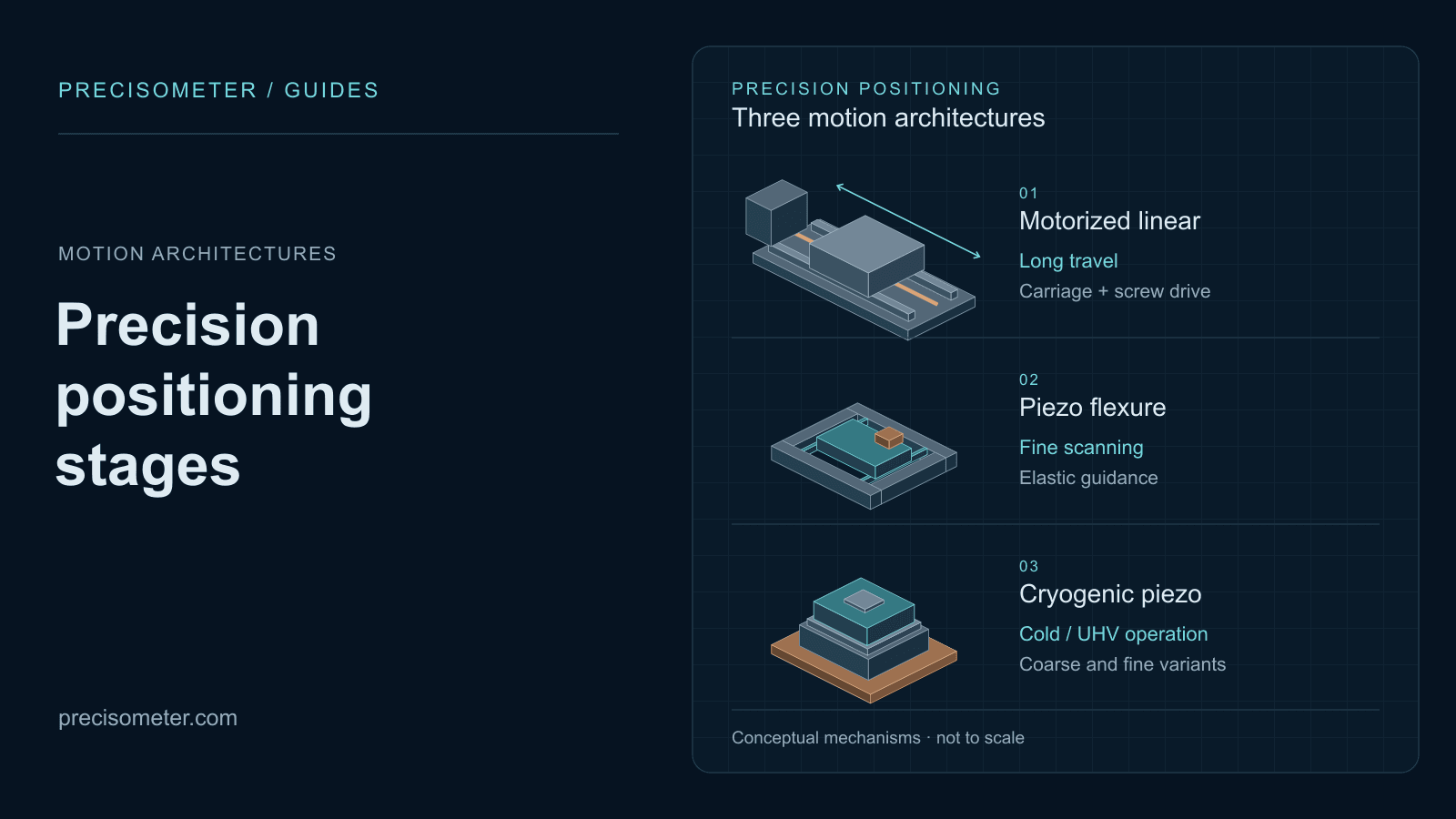 Precision motion
Match travel, resolution, speed, load, vacuum, temperature, and magnetic field requirements to motorized linear, ambient piezo, or cryogenic piezo positioning architectures.
Open guide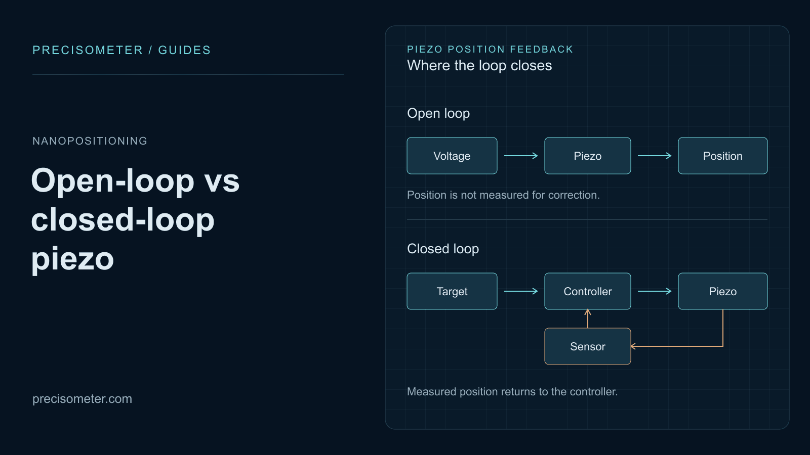 Nanopositioning
Why an open-loop piezo is wrong by 15 % of its travel, how creep grows with the logarithm of hold time, what strain-gauge and capacitive feedback actually fix — and the bandwidth and sensor noise a servo costs you in return.
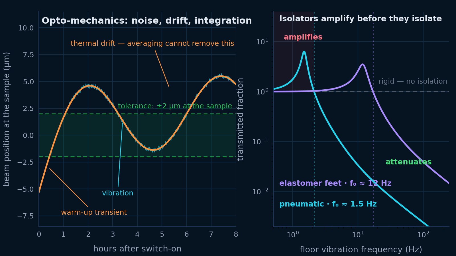
Open guide Opto-mechanicsVibration, thermal drift and mechanical integration are one problem. Budget the motion at the sample, then specify the table, the isolation, the mounts and the beam height that budget asks for.
Open guideWhere the work point sits relative to the guide, what the payload is and where its centre of gravity falls, the travel and the accuracy you need there. That is enough for us to tell you whether you need a better guide, a shorter fixture, or a different architecture entirely — and frequently the answer costs less than the stage you were about to buy.