Output-power stability
Slow mean power drift over minutes to hours
Driven by case and junction temperature changes, driver current aging, and mechanical alignment creep. Crucial for quantitative imaging and mapping.
Photonics · 16 min read
Semiconductor laser diodes are ultra-sensitive gain media: small shifts in junction temperature, drive current ripple, or stray optical reflections cause wavelength drift, high RIN, and sudden mode hops. This guide explains the physics of diode instability and how to engineer a bulletproof control architecture across all 7 stability axes.
TEC PID loop holding ±0.005 °C suppresses slow wavelength wander (~0.1 nm/°C).
Faraday isolators (>40–60 dB) eliminate back-reflection-induced mode hops and RIN spikes.
99:1 pickoff photodiode + AOM servo delivers sub-0.1% RMS power stability.
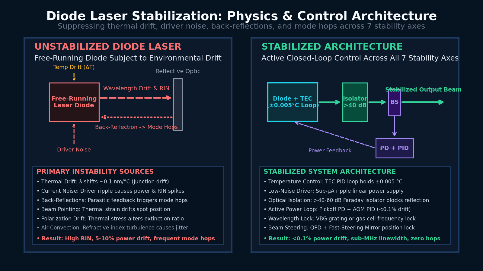
Figure 1: Free-running diode laser vulnerability (left) vs. precision closed-loop control architecture (right).
Domain Definitions
When a vendor quotes “<1% stability”, they are usually referring exclusively to slow mean power drift over 8 hours. But an experiment can easily fail due to high-frequency RIN, wavelength wander, or microphonic beam-pointing drift while power stability looks perfect. Dissect stability across all seven physical axes:
Slow mean power drift over minutes to hours
Driven by case and junction temperature changes, driver current aging, and mechanical alignment creep. Crucial for quantitative imaging and mapping.
High-frequency optical power fluctuations vs frequency
Characterized in dB/Hz. Caused by driver current ripple, spontaneous emission noise, and relaxation oscillations. Binds optical trapping and balanced detection.
Slow shift of center emission wavelength (nm / pm)
Semiconductor bandgap shrinks with temperature (~0.1 nm/°C for FP diodes). Causes spectral line shifting in Raman spectroscopy and absorption metrology.
Fast phase jitter and longitudinal mode frequency noise
Phase noise relative to an atomic transition or reference cavity. Essential for laser cooling, optical clocks, and heterodyne interferometry.
Sudden, discrete frequency jumps between longitudinal cavity modes
Occurs when internal gain curve shifts relative to cavity modes or when unshielded back-reflections create parasitic external cavities.
Angular (µrad) and spatial (µm) wander of the beam axis
Caused by thermal expansion of mounting mechanics, mirror strain, and air turbulence. Dictates single-mode fiber coupling stability.
Drift of linear polarization angle or polarization extinction ratio (PER)
Thermally induced birefringence in diode optics or fiber pigtails. Critical for polarization-sensitive ellipsometry and quantum optics.
Semiconductor laser diodes are driven by electrical injection across a forward-biased p–n junction. Electrically pumped electron-hole recombination in the active quantum-well region creates optical gain. Unlike solid-state crystal lasers (like Nd:YAG) with large upper-state lifetimes (hundreds of microseconds) and large physical cavities, diode laser cavities are tiny (typically 300 µm to 1 mm long) with carrier lifetimes under a nanosecond.
This compact size yields high wall-plug efficiency, but creates extreme interdependence between drive current, junction temperature, optical output power, and emission wavelength:
Fabry-Pérot (FP)
Cleaved crystal facets form cavity. Multi-mode output spanning 1–2 nm envelope with frequent mode hops.
VBG-Locked Diode
Volume Bragg Grating reflects narrow feedback band into FP diode, pinning center wavelength (~0.08 nm width).
DFB / DBR Diode
Etched internal grating forces single longitudinal mode emission (<2 MHz linewidth) with continuous tuning.
External-Cavity Diode (ECDL)
External diffraction grating in Littrow/Littman geometry provides sub-100 kHz linewidth and wide piezo tuning.
Because the semiconductor gain region is so small, environmental disturbances directly modulate the optical cavity parameters:
Case temperature != Junction temperature. When drive current changes, the 1-micron junction heats in microseconds, while the copper submount takes minutes to respond, creating internal thermal gradients.
Light reflected back into the diode cavity acts as a secondary external cavity (Lang-Kobayashi regime). Even -40 dB (0.01%) reflection causes severe RIN spikes, linewidth broadening, and chaotic mode hops.
Current ripple in drive electronics directly translates into intensity noise (RIN) and optical frequency modulation. Switch-mode supplies introduce high-frequency switching spikes.
Acoustic vibrations shake the laser mount, while room air convection currents alter the refractive index in free-space paths, introducing spatial phase noise and beam pointing jitter.
Temperature control is the foundation of diode laser stability. A Thermoelectric Cooler (TEC / Peltier element) sandwiched between the diode submount and a heavy aluminum or copper heatsink pumps heat actively under PID electronic control.
• Sensor Placement: Place the 10k NTC thermistor as close to the laser diode semiconductor chip as possible. Placing it far away introduces thermal diffusion delay, causing PID loop oscillation and overshoot.
• Thermal Interface: Use thin indium foil or thermal grease between diode package and heatsink. Air gaps act as thermal insulators.
• Loop Bandwidth: TEC thermal loops operate slowly (0.01 Hz to 1 Hz). Do not attempt to tune PID gains too aggressively or the Peltier element will oscillate.
• Enclosure Sealing: Enclose the laser mount in a sealed anodized aluminum housing to prevent ambient air convection from cooling the package unevenly.
Standard laboratory bench power supplies are voltage sources designed for high power delivery. They lack sub-microamp current regulation, feature high output ripple, and generate dangerous voltage turn-on/turn-off transients that will instantly destroy a laser diode junction.
Attenuator Trade-Off: Turning down drive current near threshold increases relative intensity noise (RIN) and thermal sensitivity dramatically. To reduce optical power safely, run the diode at its sweet-spot current (2–3× threshold) and attenuate output using an external Variable Optical Attenuator (VOA).
Optical feedback is the most common cause of unexplained diode laser instability in optical laboratories. When laser light reflects off a flat window, beam splitter, or FC/PC fiber connector back into the diode cavity, it interferes with the internal cavity fields.
A Faraday isolator uses a magneto-optical crystal (such as Terbium Gallium Garnet) inside a strong magnetic field sandwiched between two polarizers at 45°. Forward light passes with >93% transmission, while backward-reflected light is rotated by 45° and rejected by the input polarizer, providing >40 dB to >60 dB isolation.
Flat FC/PC connectors reflect ~4% (-14 dB) straight back down the fiber core into the diode cavity. FC/APC connectors feature an 8° angled physical contact polish, causing reflections to spill harmlessly into the fiber cladding (-60 dB reflection).
Passive thermal and current stabilization can hold a laser diode wavelength to within ~1–10 GHz over hours. But applications like atomic spectroscopy, laser cooling, optical clocks, and heterodyne interferometry require sub-megahertz frequency stability.
A small portion of the laser output passes through a gas absorption cell (e.g. Rubidium D2 line at 780 nm or Cesium at 852 nm) or a high-finesse Fabry-Pérot cavity. A high-speed PID servo compares the photodiode transmission against the absorption fringe top and feeds back an error signal to the diode current and cavity piezo, locking optical frequency to sub-MHz precision.
To eliminate both slow power drift and high-frequency intensity noise (RIN), an active feedback servo loop (“noise eater”) can be placed at the laser output:
Using an external AOM instead of modulating diode current ensures power stabilization occurs with ZERO shift in output wavelength or optical phase.
Beam-pointing drift occurs when thermal expansion in opto-mechanical mounts or thermal gradients in air cause the beam axis to wander spatially. In single-mode fiber coupling, a 1 µm translation of the focal spot reduces coupling efficiency by over 30%.
Monolithic Kinematic Mounts
Use low-expansion stainless steel mounts with fine pitch adjusters. Avoid plastic knobs or un-clamped post extension rods.
QPD Active Beam Steering
A Quadrant Photodiode (QPD) senses beam position, driving a Fast-Steering Mirror (FSM) or piezo tip/tilt mount to hold pointing to <1 µrad.
Interactive Engineering Tool
Adjust diode architecture, wavelength, ambient temperature drift, driver ripple, and optical feedback to evaluate resulting stability metrics live.
Standard laser diode cavity without wavelength-selective feedback. High thermal drift and frequent mode hops.
1.600 nm
Raman Spectral Shift: 26.0 cm⁻¹
11.37% RMS
Power Drift Status: High Drift
Net back-reflection into diode cavity: -20 dB
Severe back-reflections or thermal swings will cause sudden, discrete wavelength jumps of several GHz. Faraday optical isolation is mandatory.
Note: Simulation parameters represent typical physical scaling relationships for semiconductor diode lasers (Fabry-Pérot, VBG-locked, DFB, ECDL) under lab conditions. Always verify exact thermal and current sensitivities against diode supplier datasheets.
Diagnostic Matrix
Use this matrix to diagnose observed instability symptoms on your optical bench and implement targeted engineering corrections.
| Observed Symptom | Likely Cause | Diagnostic Test | Recommended Correction |
|---|---|---|---|
| Slow wavelength drift over hours | Inadequate TEC temperature regulation or case thermal mass drift | Monitor heatsink temperature with thermistor; track λ vs ambient room temp | Upgrade to PID TEC controller holding ±0.01 °C; isolate mount in sealed enclosure |
| Sudden, discrete wavelength & power jumps | Longitudinal mode hopping caused by thermal drift or back-reflections | Observe spectrum on high-resolution spectrograph while adjusting current slightly | Insert >40 dB Faraday optical isolator; use VBG-locked or DFB diode architecture |
| Periodic 100/120 Hz power modulation | AC mains power supply ripple injected through current driver | Inspect driver output or photodiode AC signal on oscilloscope / spectrum analyzer | Replace bench supply with low-noise linear laser driver with sub-µA current ripple |
| Excess high-frequency intensity noise (RIN spike) | Operation near laser threshold or optical feedback chaos (Lang-Kobayashi regime) | Measure RIN spectrum; check if noise drops when laser power is increased | Operate diode at 2–3× threshold; attenuate output optically using VOA or AOM |
| Fiber coupling efficiency drops over 30–60 minutes | Thermal expansion of diode mount / fiber launch causing beam-pointing drift | Measure beam position on QPD at fiber input plane during warm-up | Use monolithic kinematic mounts, PM Panda fiber, or active QPD fast-steering loop |
| Polarization extinction ratio (PER) fluctuates | Thermal stress on single-mode fiber pigtail or un-clamped window optic | Rotate analyzer polarizer; monitor PER while gently warming fiber cable | Switch to Polarization-Maintaining (PM) fiber; stress-isolate optical mounts |
| Instability appears only when sample or optic is inserted | Specular back-reflection from flat optics entering laser cavity | Tilt sample by 2–5°; check if laser stabilizes immediately | Use FC/APC 8° angled fiber connectors; place Faraday optical isolator directly after laser |
Architecture Roadmap
Select the stabilization tier that matches your measurement requirements without over-engineering basic setups.
General optical benches, fluorescence excitation, coarse alignment
Raman spectroscopy, confocal microscopy, high-resolution absorption
Atomic cooling, optical clocks, Doppler-free spectroscopy, heterodyne metrology
Catalog Hardware
Hardware solutions from our photonics catalog engineered specifically for laser diode control, optical isolation, and active feedback loops.
Laser Diode & TEC Controllers
Integrated low-noise constant-current driver and TEC thermal controller engineered specifically to eliminate driver ripple and thermal drift in 14-pin butterfly diode modules.
Optical Isolation
Magneto-optical Faraday rotators providing unidirectional isolation to prevent specular back-reflections from causing mode hops and elevated RIN.
Active Power Control
Fast external intensity actuator for active photodiode PID feedback loops ("noise eater"), suppressing high-frequency RIN without altering diode current or wavelength.
Optical Attenuation
Allows scientists to attenuate laser power at the sample while maintaining the laser diode at its optimal, low-noise drive current setpoint.
Wavelength-Locked Sources
Volume Bragg Grating (VBG) locked diode laser providing immunity against thermal wavelength drift for Raman spectroscopy and metrology.
Single-Frequency Sources
Ultra-narrow linewidth single-frequency laser sources engineered for interferometry, heterodyne detection, and atomic physics.
Related Technical Guides
Linewidth vs spectral width, RIN, M², and coherence length — how to read datasheets accurately.
Vibration isolation, thermal drift, and rigid kinematic mounting for optical benches.
Application deep dive where RIN noise and beam-pointing stability dictate trap stiffness.
Why wavelength stability and VBG locking are critical for keeping the Raman spectral axis calibrated.
Frequently Asked Questions
A semiconductor laser diode chip reaches thermal equilibrium with its immediate submount in seconds, but the surrounding copper heatsink, TEC, thermistor interface, and package housing take 15 to 30 minutes to eliminate internal thermal gradients. Operating before thermal equilibrium is reached results in continuous wavelength drift (~0.1 nm/°C) and beam-pointing wander. Always enforce a minimum 20-minute warm-up period for quantitative measurements.
Semiconductor bandgap energy decreases as temperature rises, which shifts the peak optical gain spectrum toward longer wavelengths (red shift) at roughly +0.25 to +0.3 nm/°C for GaAs/InGaAs materials. Additionally, thermal expansion alters the optical cavity length of the diode semiconductor chip, shifting cavity modes by approximately +0.06 to +0.08 nm/°C. For free-running Fabry-Pérot diodes, this combined thermal coefficient is approximately +0.1 nm/°C.
No. While drive current affects both optical power and junction temperature, current control alone cannot compensate for ambient temperature swings or heatsink thermal lag. Without a Thermoelectric Cooler (TEC) active feedback loop holding the mount temperature constant, ambient room shifts will override any current regulation.
Mode hopping occurs when the peak of the semiconductor gain curve shifts relative to the discrete longitudinal Fabry-Pérot cavity modes, or when an unshielded external optical reflection forms a secondary parasitic cavity (the Lang-Kobayashi effect). When a neighboring cavity mode achieves higher optical gain, the laser suddenly jumps to that mode, causing an instantaneous discontinuity in wavelength (several GHz) and output power.
If your optical path contains flat mirrors, beam splitters, sample windows, or flat-polished FC/PC fiber connectors, yes. Even 0.1% (-30 dB) back-reflection into the laser diode cavity degrades the optical spectrum, elevates relative intensity noise (RIN) by 20–30 dB, and triggers mode hopping. Faraday optical isolators provide >40 dB unidirectional isolation, protecting the laser cavity.
For slow drift correction, modulating drive current is simple and effective. However, altering drive current also alters junction temperature and output wavelength. If your experiment requires strict wavelength or frequency stability (such as Raman spectroscopy or interferometry), power stabilization must actuate an external Acousto-Optic Modulator (AOM) or Variable Optical Attenuator (VOA) rather than the diode current.
Wavelength locking (such as using a Volume Bragg Grating) pins the center emission wavelength to within a broad band (e.g. ~0.08 nm or 40 GHz) and prevents thermal wander. Frequency locking uses active PID electronic feedback against a sharp atomic transition (e.g., Rubidium D2 line) or high-finesse Fabry-Pérot cavity to lock the optical phase and narrow the linewidth to sub-MHz or kilohertz precision.
No. Thermoelectric coolers have a thermal response bandwidth of under 1 Hz due to heat capacity and thermal diffusion lag. They are strictly designed for slow thermal drift correction (DC to 0.1 Hz). High-frequency intensity noise (10 Hz to 100 MHz) must be suppressed using low-noise current drivers or an active photodiode feedback loop actuating an AOM.
Use pigtailed modules with Polarization-Maintaining (PM) Panda fiber terminated with 8° angled FC/APC connectors. Ensure the butterfly package is clamped securely to a TEC-controlled mounting block, and secure the fiber cable to prevent mechanical vibration and thermal stress.
Place a high-speed photodiode or power meter with a 99:1 pickoff beam splitter directly at the laser output (before any downstream optics or sample holders). If the pickoff power is stable while the signal at your detector drifts, the instability originates in your downstream opto-mechanics, sample positioning, or thermal expansion of optical mounts.
Describe your wavelength, required power stability, RIN noise floor, and linewidth requirements — our optical engineers will configure a customized stabilization package.