Compare the details
Technical specifications
Compare the listed configurations and match the specifications to your setup.
Jump to a specification table (2)
22 specification rows.
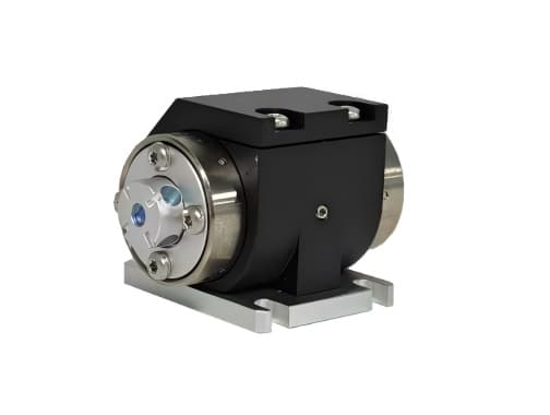
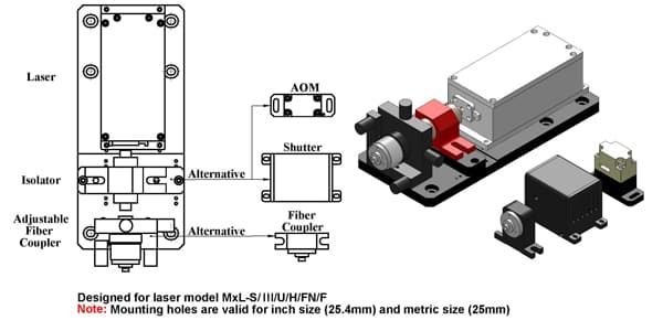
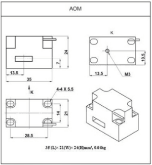
Acousto-optic modulator
12 entries| Parameter | Specification |
|---|---|
| Wavelength | 450-700nm |
| Optical power | Typical <1W (@1.0mm) |
| Transmission | 93% |
| Center frequency | 100MHz |
| Diffraction efficiency | 80% |
| Active aperture | 1.0mm |
| Extinction ratio | ≥1000:1 |
| Pulse repetition frequency | 4MHz |
| RF power | 1.2W |
| Input impedance | 50Ω |
| Controller drive voltage | 24VDC |
| External modulation | TTL/Analog |
Mechanical shutter
10 entries| Parameter | Specification |
|---|---|
| Aperture Diameter | 4.0mm |
| Typical Beam Diameter | 2.0mm |
| Operating Frequency Range | 0-10Hz |
| Maximum Laser Power | <3W |
| Rise Time | ~8ms |
| Fall Time | ~8ms |
| Delay d | ~18ms |
| Operating Temperature | 15-40℃ |
| External Modulation | TTL |
| Drive Voltage | 5VDC/ 12VDC |
Build around your experiment
What to specify
Share these details with your enquiry so we can match the component to your optical setup.
- 01Laser wavelength, optical power and beam size.
- 02Required timing, modulation depth and electrical signal levels.
- 03Driver, control interface, mounting and thermal requirements.
Technical FAQ
Configuration questions for AOM & Shutter
How should the AOM & Shutter be included in an optical power budget?
Wavelength: 450-700nm · Extinction ratio: ≥1000:1. Check the Laser components and accessories passband, insertion loss, return loss and power handling at the actual source wavelength; a nominal telecom-band label is not a substitute for the configured range.
Does the AOM & Shutter require a controller?
Controller drive voltage: 24VDC · Drive Voltage: 5VDC/ 12VDC. Match supply voltage, analog or digital command range, connector pinout and default optical state to the instrument interlock. Confirm the unpowered state explicitly — it decides what happens to the link on a power failure.
Technical documents
Keep the specifications at hand when planning your setup.
Download datasheet (PDF)Talk through your setup
Find the right configuration
Add this component to your enquiry and include your requirements. We will help specify the variant, interfaces and mounting.