Compare the details
Technical specifications
Compare the listed configurations and match the specifications to your setup.
Jump to a specification table (4)
29 specification rows.
System architecture
6 entriesScroll horizontally to compare all columns
| Subsystem | Available configuration | Integration purpose |
|---|---|---|
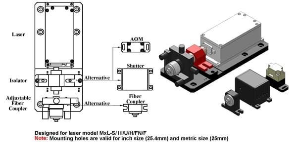
| Laser sources | Single- or multi-wavelength | Builds the excitation set required by the instrument |
| Thermal management | TC-01 active control or TC-02 passive heat sink | Stabilizes source temperature and removes waste heat |
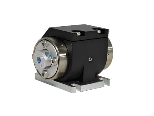
| Optical isolation | Free-space Faraday isolator | Reduces destabilizing back-reflection into the laser |
| Beam gating | Mechanical shutter | Provides TTL-controlled exposure or safety gating |
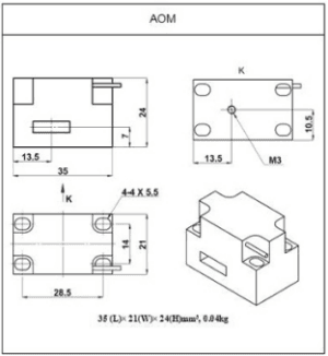
| Fast modulation | Acousto-optic modulator | Controls intensity at higher repetition rates |
| Beam delivery | Free-space or fiber coupling | Matches the platform to the downstream optical path |
Free-space isolator options
4 entriesScroll horizontally to compare all columns
| Model | Center wavelength | Operating range | Peak transmission | Clear aperture | Isolation |
|---|---|---|---|---|---|
| C-HP-3-405 | 405 nm | ±10 nm | >90% | 3 mm | ≥25 dB |
| C-HP-2-532 | 532 nm | ±10 nm | >93% | 2 mm | ≥25 dB |
| C-HP-3-633 | 633 nm | ±10 nm | >93% | 3 mm | ≥25 dB |
| C-HP-2.3-785 | 785 nm | ±10 nm | >93% | 2.3 mm | ≥25 dB |
Mechanical shutter interface
7 entries| Parameter | Listed value |
|---|---|
| Aperture diameter | 4.0 mm |
| Typical beam diameter | 2.0 mm |
| Operating frequency | 0–10 Hz |
| Maximum laser power | <3 W |
| Rise / fall time | Approximately 8 ms / 8 ms |
| External modulation | TTL |
| Drive voltage | 5 VDC or 12 VDC |
Acousto-optic modulator interface
12 entries| Parameter | Listed value |
|---|---|
| Wavelength | 450–700 nm |
| Optical power | Typically <1 W at 1.0 mm beam diameter |
| Transmission | 93% |
| Center frequency | 100 MHz |
| Diffraction efficiency | 80% |
| Active aperture | 1.0 mm |
| Extinction ratio | ≥1000:1 |
| Pulse repetition frequency | 4 MHz |
| RF power | 1.2 W |
| Input impedance | 50 Ω |
| Controller drive voltage | 24 VDC |
| External modulation | TTL or analog |
Build around your experiment
What to specify
Share these details with your enquiry so we can match the component to your optical setup.
- 01Laser wavelength, optical power and beam size.
- 02Required timing, modulation depth and electrical signal levels.
- 03Driver, control interface, mounting and thermal requirements.
Technical FAQ
Configuration questions for Multi-function Optical System
What cooling does the Multi-function Optical System require?
Thermal management: TC-01 active control or TC-02 passive heat sink / Stabilizes source temperature and removes waste heat. Provide the stated cooling method and keep the laser-head base thermally coupled; temperature drift moves wavelength, output power and beam pointing.
What beam does the Multi-function Optical System deliver?
Typical beam diameter: 2.0 mm. Size the downstream optics from the stated beam diameter and divergence rather than from the aperture of the housing, and confirm the polarisation state before specifying isolators or polarising optics.
Technical documents
Keep the specifications at hand when planning your setup.
Request the technical documentation for your configuration with your enquiry.
Talk through your setup
Find the right configuration
Add this component to your enquiry and include your requirements. We will help specify the variant, interfaces and mounting.