Photoelectric Testing Systems
PhotoelectricTesting Systems
Control the illumination. Measure electrical performance. See how a device responds across wavelength, position and time — with systems for solar cells, photodetectors and imaging sensors.
- 13
- Systems & instruments
- 200–2500 nm
- Spectral coverage
- 40 µm
- Microdevice probe spot
- 300 × 300 mm
- Large-area mapping
Illumination, measurement and calibration
Across configured spectral-response systems
DSR300 spectral responsivity platform
Largest SCS800 scan-field option
Illuminate and measure a solar cell
Choose SolarIV for a complete light and dark I–V setup. For a separate illumination source, compare xenon and LED simulators; use QE-B1 to calibrate irradiance.
Resolve response by wavelength
Use SCS600 or SCS1000 for photovoltaic quantum efficiency, DSR600 for detector responsivity, and DSR300 for small active areas.
Find spatial or temporal losses
DSR500-LBIC images microscopic photocurrent; SCS800 maps larger cells. DSR800 measures transients, DSR600-PDE single-photon efficiency, and DSR900 camera performance.
Choose your measurement
Solar Simulation & I–V Testing
Controlled illumination, photovoltaic electrical measurements and reference-cell calibration.
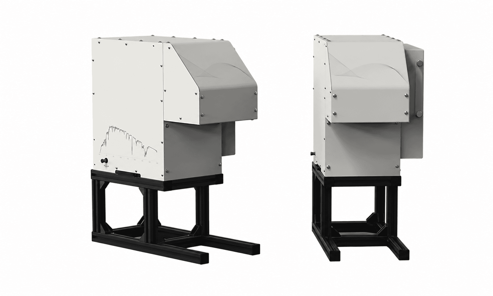
Photovoltaic I–V characterisation
SolarIV
Measure illuminated and dark I–V curves, conversion efficiency, fill factor and series and shunt resistance. SolarIV-150A and SolarIV-300A combine a solar simulator, digital source meter, reference cell and analysis software.
- Illuminated area
- 40 × 40 / 60 × 60 mm
- Measurements
- Light & dark I–V
- Reference cell
- QE-B1 included
Xenon solar simulation
Sirius
Sirius solar simulators use short-arc xenon lamps with AM1.5G filtering, adjustable irradiance and a motorised shutter. Select a 40 × 40 mm or 60 × 60 mm illuminated field and the output direction required by the experiment.
- Irradiance adjustment
- 0.2–1.2 sun
- Illuminated area
- 40 / 60 mm square
- Non-uniformity
- ≤ 2%
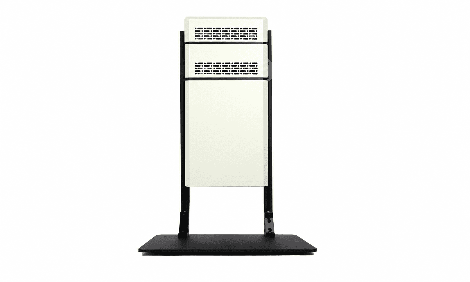
Programmable LED solar simulation
SS-L140 / SS-L300
A 21-wavelength LED array covers 350–1100 nm with independently controlled channels. SS-L140 and SS-L300 provide 140 mm and 300 mm square illuminated areas for steady-state photovoltaic and materials testing.
- Spectral range
- 350–1100 nm
- LED wavelengths
- 21
- Irradiance
- 100–1200 W/m²
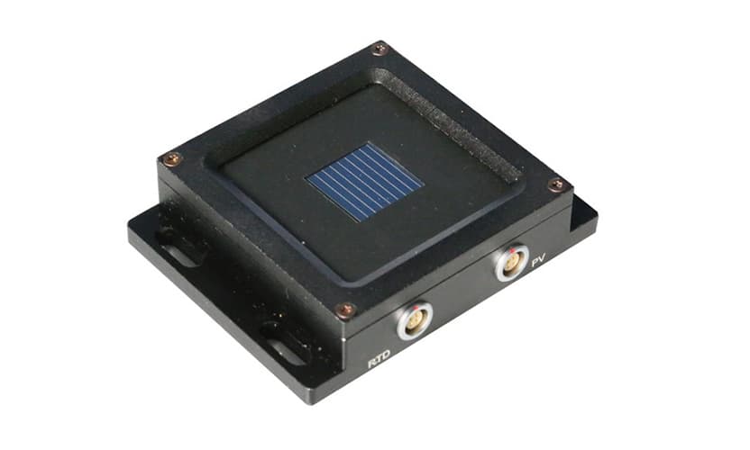
Solar irradiance calibration
QE-B1
QE-B1 is a monocrystalline silicon reference solar cell for setting the irradiance of a solar simulator before photovoltaic I–V measurements. Filter options adapt the reference response to the measurement.
- Cell material
- Monocrystalline Si
- Purpose
- Irradiance calibration
- Options
- Optical filters
Choose your measurement
Spectral Response & Quantum Efficiency
Measure response versus wavelength, from microdevices to automated photovoltaic characterisation.
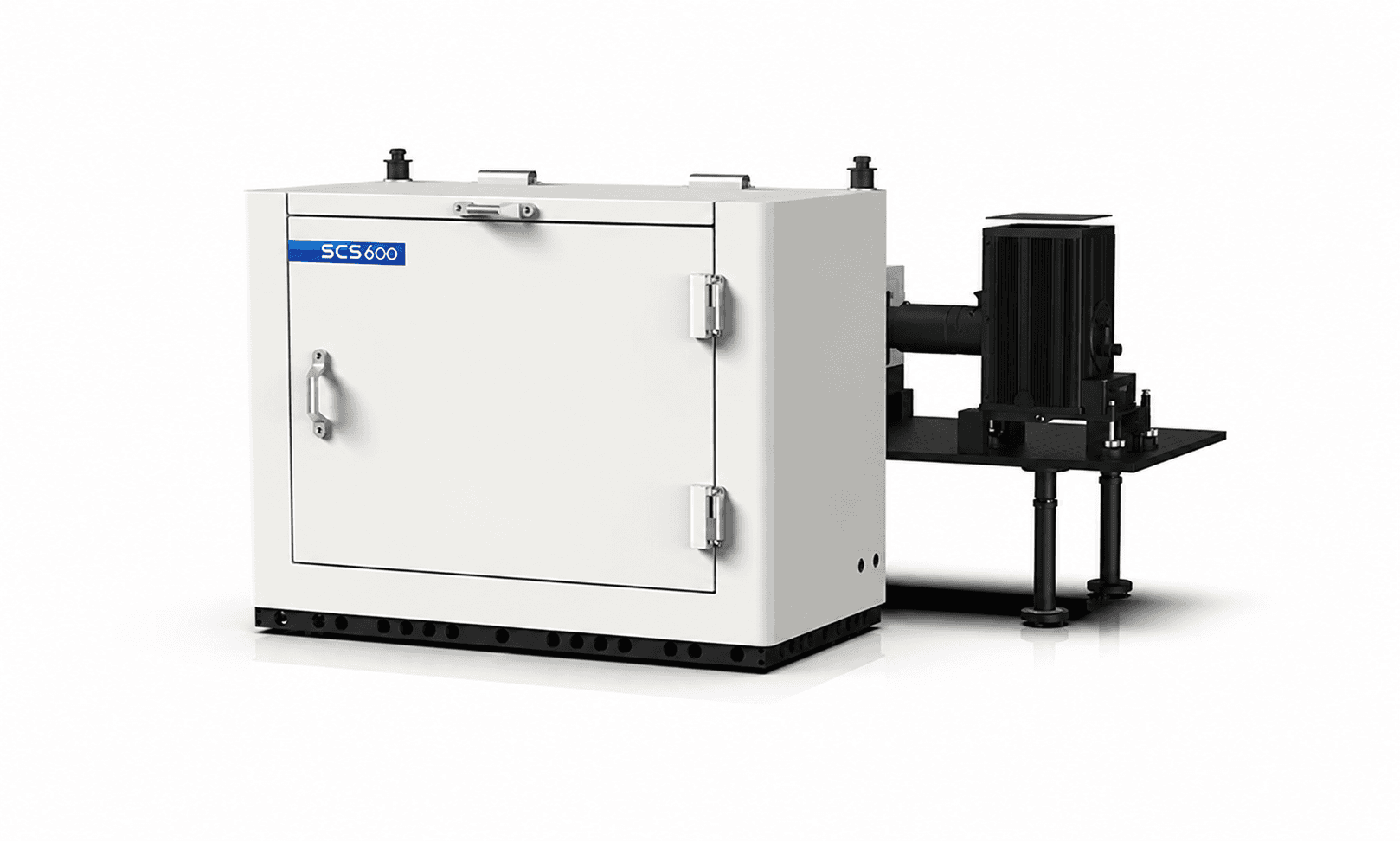
Solar-cell EQE, IQE and IPCE
SCS600
SCS600 measures spectral response and quantum efficiency with reflective optics, camera-assisted alignment and AC/DC acquisition. Xenon, tungsten-halogen and dual-source configurations support different wavelength ranges.
- Published measurement range
- 250–1700 nm
- Dual-source option
- To 2500 nm
- Minimum spot
- ≤ 1 mm
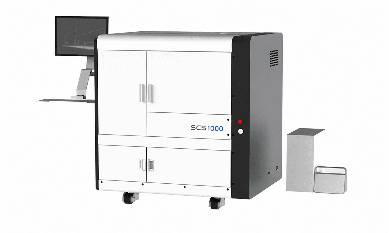
Automated spectral response and mapping
SCS1000
SCS1000 is an integrated quantum efficiency platform with software-controlled measurement modes, reference-detector switching and spot selection. Measures spectral response, EQE and IQE with optional reflectance, transmittance and mapping functions.
- Minimum spot
- < 1 mm
- Operation
- Automated switching
- Acquisition options
- AC / DC
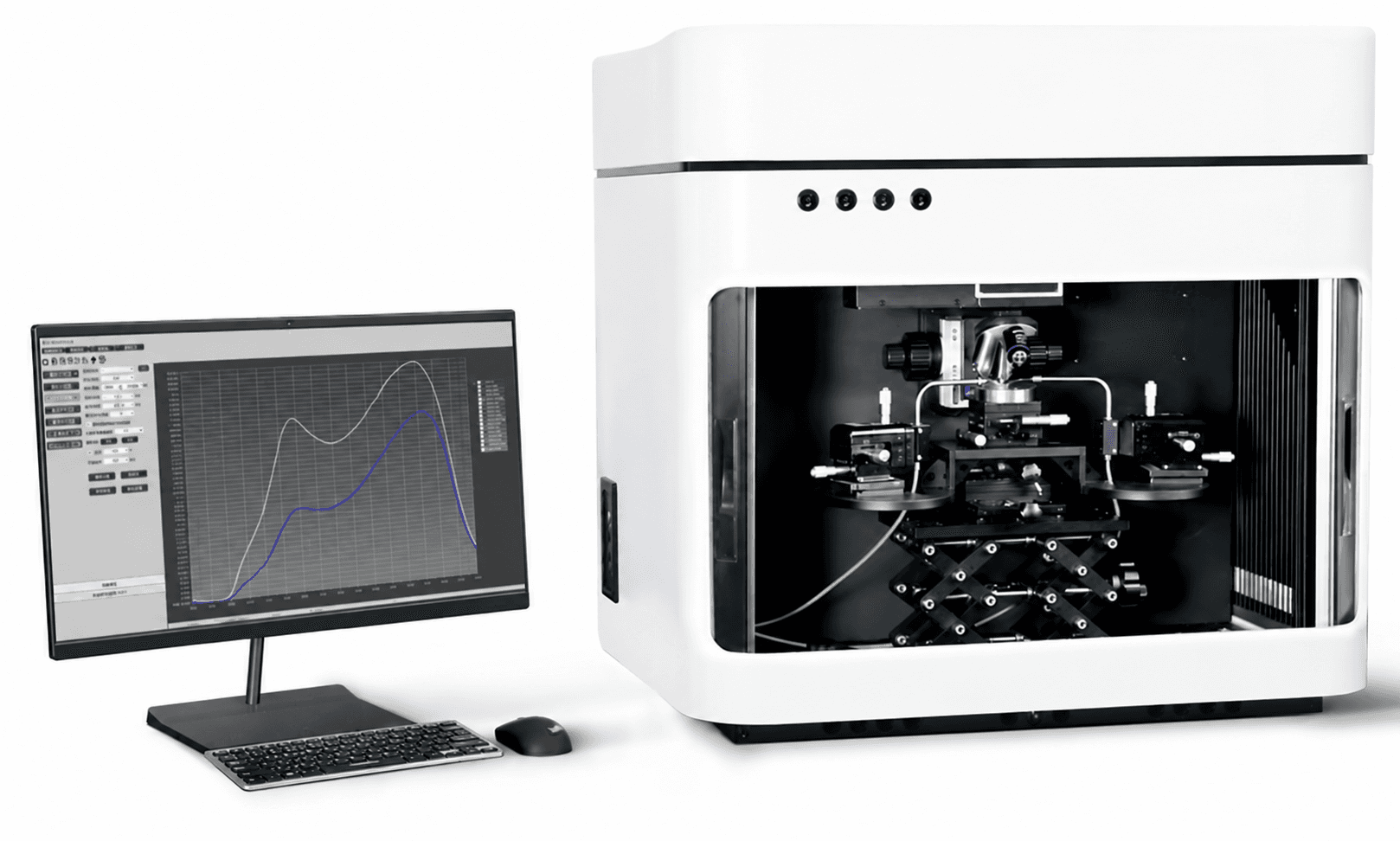
Microdevice photoelectric characterisation
DSR300
DSR300 is a microscope-based platform for spectral responsivity, external quantum efficiency, photocurrent mapping and response-rate measurements. A 40 µm probe spot targets small detector areas and microstructured devices.
- Probe spot
- 40 µm
- Measurements
- SR & EQE
- Spatial testing
- LBIC mapping
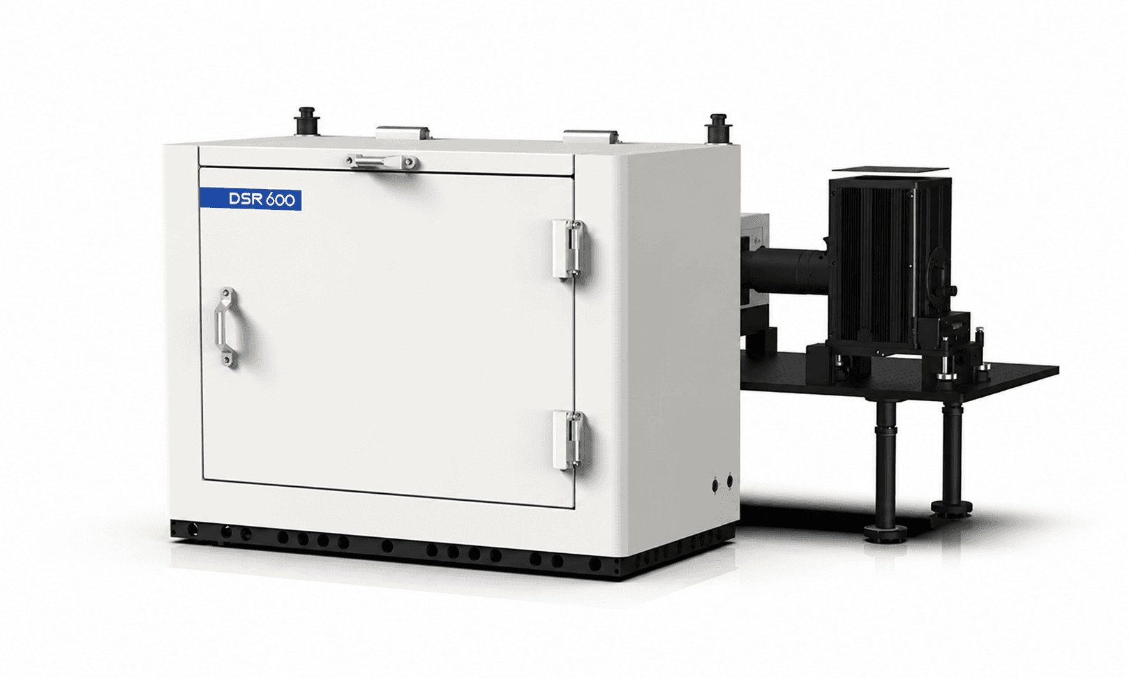
Detector spectral responsivity
DSR600
DSR600 automates spectral responsivity and quantum efficiency characterisation for UV, visible and near-infrared detectors. Configurations cover 200–2500 nm and support photovoltaic devices, bias-dependent I–V and tandem-cell EQE measurements.
- Configured coverage
- 200–2500 nm
- Primary measurements
- SR & QE
- Electrical tests
- Light / dark I–V
Choose your measurement
Photocurrent Imaging & Defect Mapping
Locate spatial variations across microscopic devices and large-area solar cells.
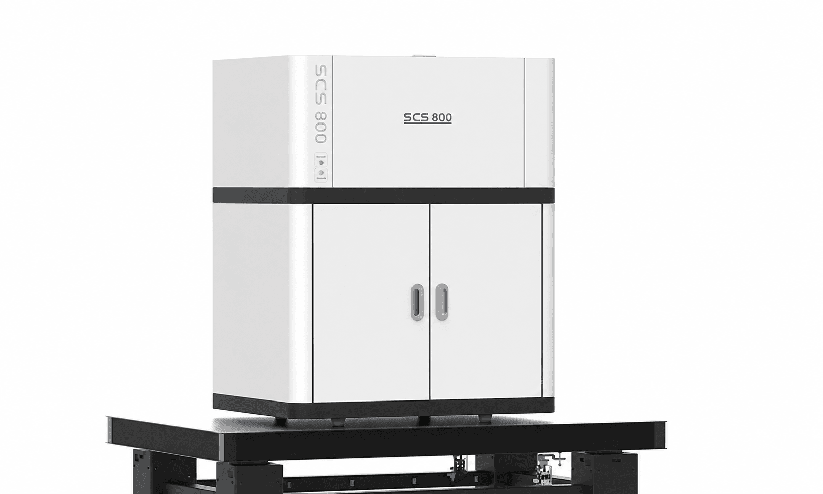
Large-area photocurrent mapping
SCS800
SCS800 uses galvanometer-scanned laser excitation to map photocurrent and photovoltage across solar cells and photoelectric materials. Field options up to 300 × 300 mm support spatial uniformity studies and defect localisation.
- Largest scan field
- 300 × 300 mm
- Specified resolution
- < 100 µm
- Standard laser
- 532 nm
Microscopic LBIC mapping
DSR500-LBIC
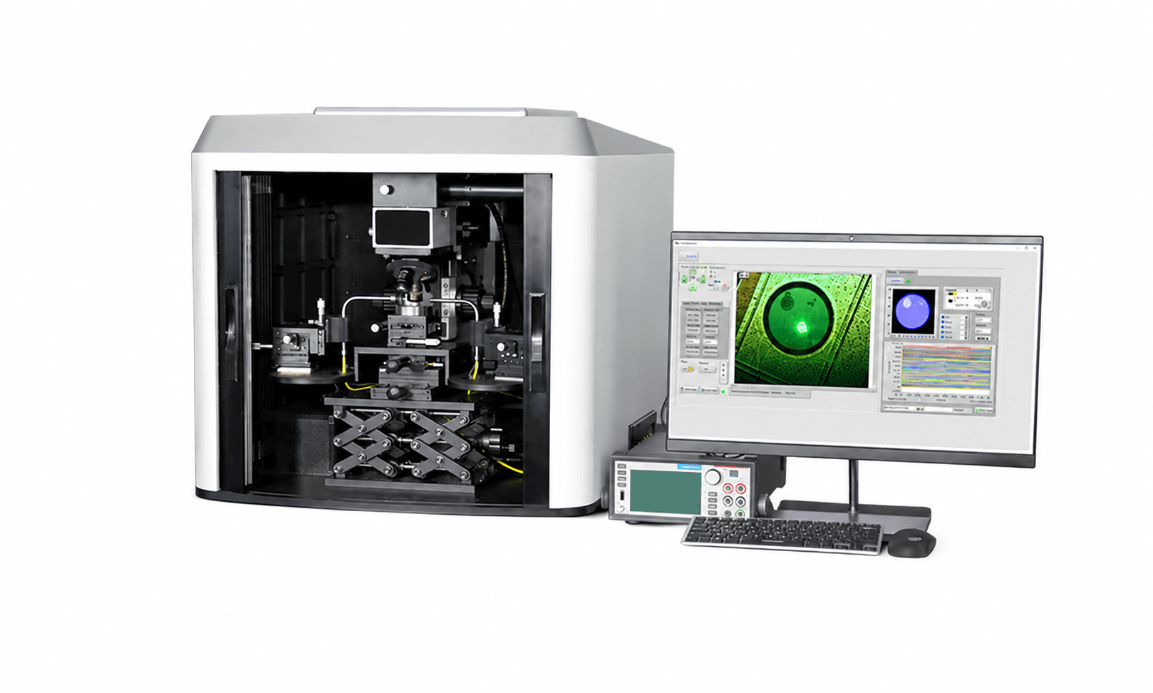
DSR500-LBIC uses a galvanometer-scanned microscope to record local photocurrent and I–V curves while the sample remains stationary. The standard 20× objective provides a 260 × 200 µm scan field, with selectable scan steps down to 0.2 µm.
- Scan field at 20×
- 260 × 200 µm
- Minimum scan step
- 0.2 µm
- Laser spot
- 2 µm
Choose your measurement
Transient Response & Detector Calibration
Characterise device dynamics, single-photon efficiency and camera performance.
Transient photocurrent and photovoltage
DSR800
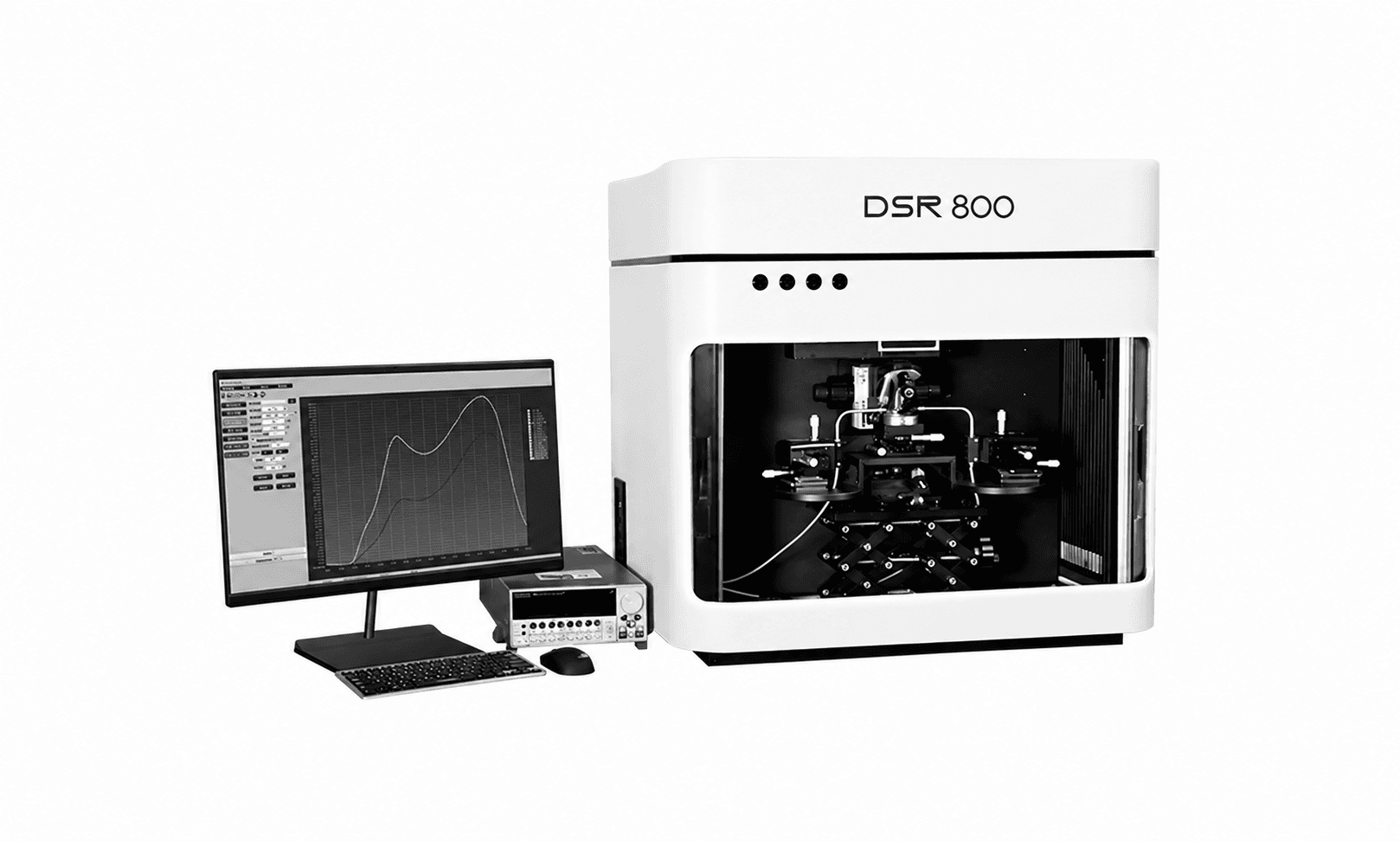
DSR800 uses pulsed optical excitation and configurable acquisition to measure transient photocurrent, photovoltage and response times. Microscope optics, selectable lasers and probe fixtures support detector and photovoltaic dynamics experiments.
- Acquisition options
- 4 ns–400 ps
- Channels
- 2 or 4
- Sampling option
- 2.5 GS/s
Single-photon detector calibration
DSR600-PDE
DSR600-PDE measures photon detection efficiency versus wavelength by comparing a photon-counting detector with a calibrated reference through an integrating sphere. Supports SPAD, SiPM, PMT and other single-photon-sensitive detectors.
- Standard wavelength range
- 300–1100 nm
- Extended option
- To 2500 nm
- Measurements
- PDE, SR & EQE
CCD and CMOS sensor evaluation
DSR900
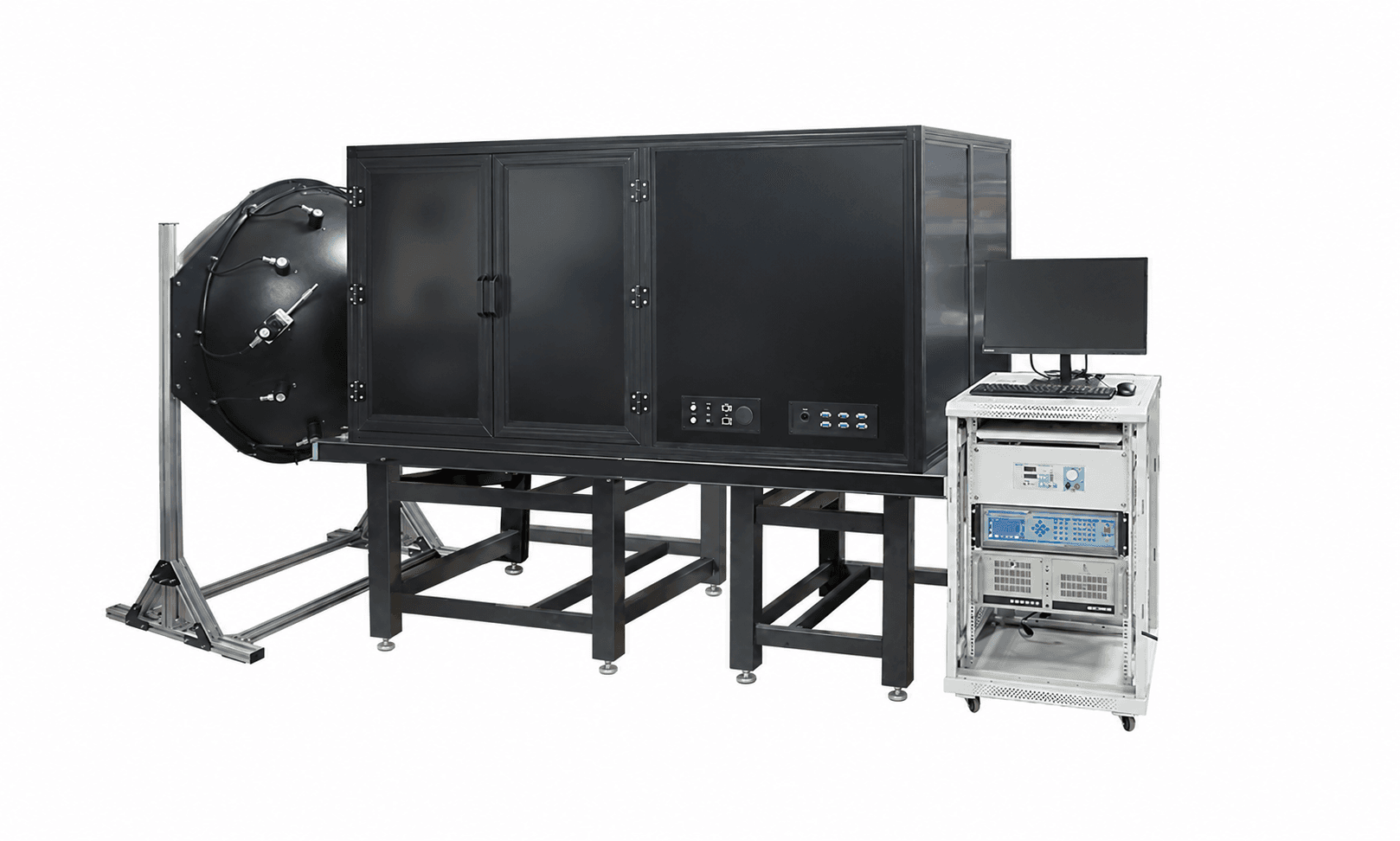
DSR900 automates camera and imaging-sensor characterisation with uniform monochromatic illumination, a dark enclosure and analysis software. Supports EMVA 1288 measurement workflows for visible and near-infrared cameras.
- Camera types
- CCD & CMOS
- Workflow
- EMVA 1288
- Monochromatic sphere
- 200 mm diameter
Side by side
Find the right measurement
Ranges and functions depend on the selected source, acquisition module and sample fixture.
| System | What it measures / provides | Range / scale | Configuration |
|---|---|---|---|
| SolarIV | Light / dark I–V, efficiency, fill factor | 40 × 40 or 60 × 60 mm illumination | Simulator + source meter + reference cell; stage separate |
| Sirius | Solar illumination | 40 × 40 or 60 × 60 mm field | Xenon source; direction selected by model |
| SS-L140 / SS-L300 | Programmable steady-state solar illumination | 350–1100 nm; 140 / 300 mm square field | 21 LED wavelengths; 3 cm working distance |
| QE-B1 | Solar irradiance reference | Filter and calibration dependent | Monocrystalline silicon reference cell |
| SCS600 | EQE, IQE, IPCE and spectral response | 250–1700 nm; configuration-dependent extension to 2500 nm | Xenon, halogen or dual source; ≤ 1 mm spot |
| SCS1000 | Automated EQE / IQE, spectral response and mapping | Defined by source and calibrated reference detectors | Integrated mobile enclosure; AC/DC module options |
| DSR300 | Microdevice SR, EQE, I–V and photocurrent mapping | 40 µm probe spot; spectral range by configuration | Microscope and adjustable probe station |
| DSR600 | Detector SR, QE and photovoltaic EQE | 200–2500 nm across configured options | Automated spectral scanning with reference calibration |
| SCS800 | Photocurrent / photovoltage defect maps | Up to 300 × 300 mm; < 100 µm resolution | 532 nm standard; additional laser and cooled-stage options |
| DSR500-LBIC | Microscopic photocurrent and I–V mapping | 260 × 200 µm field; 2 µm laser spot | 20× objective; 0.2–30 µm scan steps |
| DSR800 | Transient photocurrent / voltage, decay and charge extraction | 4 ns–400 ps acquisition options | Pulsed sources; 2 / 4-channel acquisition |
| DSR600-PDE | Single-photon PDE versus wavelength | 300–1100 nm; extension to 2500 nm | Integrating sphere, calibrated reference and pulse counting |
| DSR900 | Camera noise, linearity, dynamic range and uniformity | Component-dependent UV / visible / NIR coverage | Uniform illumination, dark enclosure and automated reports |
Build the test around your device
Share the active area, wavelength range, contact layout and signals you need to measure. We will help select the optics, source and acquisition configuration.
Discuss your measurement