Back to Home
← All guides

Nanopositioning · 19 min

Piezo drive architectures

Piezo ceramic strains by about one part in a thousand. A 20 mm stack gives you 20 µm, and that is the entire budget. Every mechanism in this guide is a different answer to what you do when you need more — and each answer wins a different experiment.

Direct stackAmplified flexureTube scannerStick-slipWalkingUltrasonic

Start here

One tenth of one percent, and six ways around it.

Ask what a piezo stage costs and you get a catalogue. Ask how it moves and you get an answer that predicts almost everything else about it — how far it goes, how fast, how stiff it is, whether it holds position when you switch it off, and whether it belongs in a cryostat.

The constraint underneath all of it is that a poled ceramic strains by roughly 0.1 to 0.15 percent of its length. That is a superb actuator over a few tens of micrometres: friction-free, infinitely divisible, stiff enough to resonate in the tens of kilohertz. It is also a hard ceiling. You cannot drive it harder, because the field is already at the limit the ceramic tolerates.

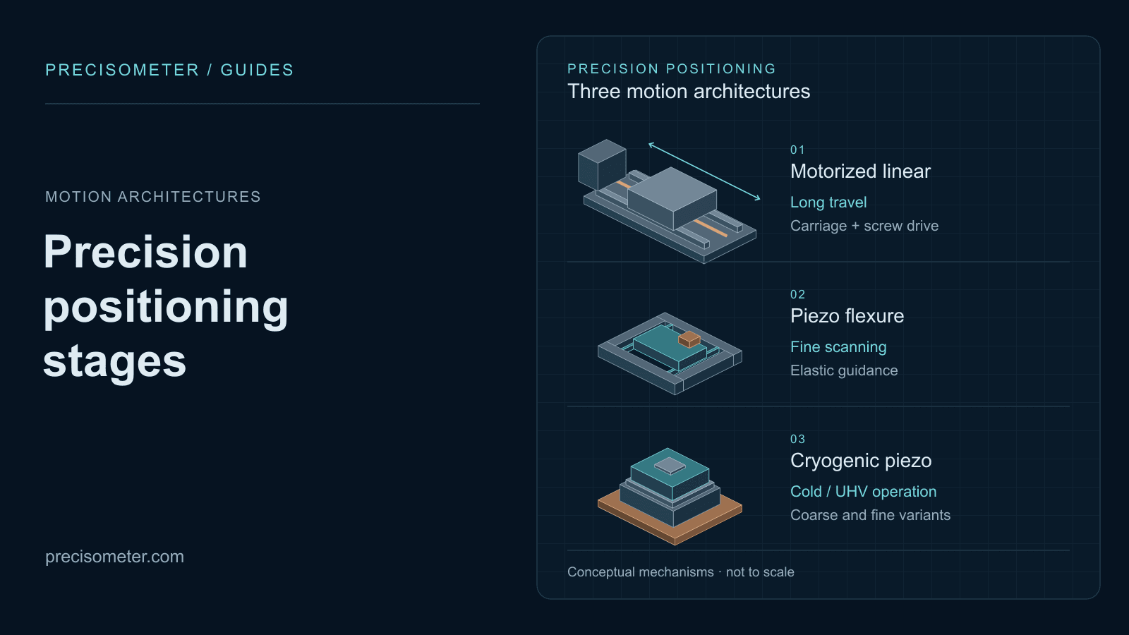
So there are two families. The analogue architectures accept the ceiling and make the most of the strain: a bare stack, a tube, or a stack driving a flexure that trades force for displacement. Motion is continuous, deterministic and friction-free, and travel stops at a few hundred micrometres. The stepping architectures give up on continuity and accumulate the strain instead — stick-slip, walking and ultrasonic drives all convert repeated small deformations into unbounded travel through a friction interface.

Everything else follows from that split. Analogue stages need to be energised to hold position; stepping stages hold by friction at zero power. Analogue motion is smooth and repeatable; stepping motion is quantised and needs an encoder before it means anything. Analogue actuators lose half their stroke at 4 K; stepping drives just take smaller steps. Choose the family first, and the model number becomes a short list.

The six mechanisms

How the motion is actually made.

ArchitectureMotion mechanismTravelIncremental motionHolds at 0 VWhat it wins
Direct stackAnalogueCo-fired ceramic layers strain along the field5–60 µm< 0.1 nmNoForce, stiffness and speed over a very short stroke. Steering mirrors, cavity tuning, dither, indentation.
Amplified flexureAnalogueA stack drives a monolithic lever or bridge flexure15–500 µm0.1–0.5 nmNoFriction-free scanning. Objective focus, sample raster, closed-loop nanopositioning.
Tube scannerAnalogueQuadrant electrodes bend a tube in XY, extend it in Z1–100 µm< 0.1 nmNoCompact, cheap, fast. Scanning probe microscopy, where curvature and cross-coupling are tolerable.
Stick-slip inertialSteppingSawtooth drive: slow stick carries the slider, fast slip resets3–200 mm1–2 nm with an encoderYesLong travel in small volumes, at zero holding power. Cryostats, UHV, compact multi-axis stacks.
Walking driveSteppingLeg pairs clamp and shear in quadrature, never letting go5–100 mm< 1 nmYesLong travel with high force and stiffness. Metrology frames, lithography, heavy nanopositioning.
Ultrasonic resonantSteppingA resonator at 40–200 kHz traces an ellipse against the sliderUnbounded30–100 nmYesSpeed. Hundreds of mm/s for autofocus, screening and industrial alignment.

The shaded rows are the stepping family. Notice that the column separating them from the analogue rows most cleanly is not travel or resolution — it is whether the axis stays put when you cut the power.

Inside a stick-slip step

Drive the piezo with a sawtooth. On the slow ramp, static friction holds a slider against the actuator and carries it along. On the fast flyback the actuator retracts faster than friction can drag the slider with it, so the slider slips and stays roughly where it was. Net motion per cycle: tens to hundreds of nanometres. Repeat at a few kilohertz and you have millimetres per second.

Two consequences matter more than the mechanism itself. The friction that couples the drive also locks the axis when the drive stops, so the stage holds with no power and no dissipation. And the step size is the outcome of a stochastic friction process, so it varies with load, direction and temperature — which is why the encoder, not the motor, is what gives these stages a resolution.

Walking, and why it costs more

A walking drive uses several leg pairs driven in quadrature: while one pair clamps and shears the slider forward, the other lifts, returns and takes over. The slider is never released, so there is no slip, no lost motion, and the full clamping force — often hundreds of newtons — holds the axis at all times, powered or not.

In exchange you need four or more synchronised high-voltage channels running a carefully shaped waveform, and the mechanism itself is a precision assembly. It is the only architecture that gets unbounded travel, sub-nanometre motion and high stiffness at once, and it is priced accordingly.

Interactive

Put your requirement against all six.

Travel, incremental motion, payload, duty cycle and environment, evaluated against every mechanism at once. The interesting result is not which one passes — it is how often nothing does, and how quickly a coarse-plus-fine stack solves what no single stage can.

Architecture selector

Which drive mechanism can service this axis

Six architectures against your travel, resolution, payload, duty cycle and environment. When nothing passes, the panel splits the requirement into a coarse and a fine axis — which is usually the correct answer rather than a compromise.

2.00 mm

Total range of one axis. Analogue actuators stop at a few hundred micrometres; stepping motors do not stop.

2.0 nm

The smallest move you need to make reliably — not the display resolution of the controller.

300 g

Everything the axis carries, including the stages above it in a stack.

Duty cycle
Environment

Dynamic range you are asking for

10^6

Travel divided by incremental motion. Analogue actuators live around 10^5. Add an encoder to a stepping motor and you reach 10^7. Beyond that you are building a stack.

Piezo tube scanner

Analogue
range 10^6

A single tube with quadrant electrodes. XY from bending, Z from extension.

  • travel 100 µm
  • step 0.10 nm
  • load 50 g
  • ambient good
  • stepping ok
  • up to 1 mm/s

Direct piezo stack

Analogue
range 10^6

Co-fired ceramic layers pushing along their own axis. No mechanism at all.

  • travel 60.0 µm
  • step 0.050 nm
  • load 20 kg
  • ambient good
  • stepping good
  • up to 20 mm/s

Amplified flexure scanner

Analogue
range 10^6

A stack driving a monolithic lever or elliptical flexure that multiplies its stroke.

  • travel 500 µm
  • step 0.10 nm
  • load 2.0 kg
  • ambient good
  • stepping good
  • up to 5 mm/s

Stick-slip inertial motor

Steppingself-locking
range 10^8

A sawtooth drive: slow expansion carries the slider by friction, fast retraction slips under it.

  • travel 200 mm
  • step 1.0 nm
  • load 5.0 kg
  • ambient good
  • stepping good
  • up to 5 mm/s

Ultrasonic resonant motor

Steppingself-locking
range 10^7

A resonator driven at 40–200 kHz whose contact tip traces an ellipse against the slider.

  • travel 300 mm
  • step 30 nm
  • load 3.0 kg
  • ambient good
  • stepping good
  • up to 300 mm/s

Walking (legged) piezo drive

Steppingself-locking
range 10^9

Multiple leg pairs clamping and shearing in quadrature, so the slider is always held.

  • travel 100 mm
  • step 0.10 nm
  • load 50 kg
  • ambient good
  • stepping good
  • up to 10 mm/s

What to build

A single stick-slip inertial motor covers this. Travel is unbounded because steps accumulate, and the drive dissipates power only while it moves — which is why cryostats and UHV chambers are full of them. The open-loop step is not a resolution: it changes with load, direction and temperature. An encoder is what makes the number real. Rows are ordered by drive complexity and cost, so this is the cheapest architecture that meets every constraint rather than the most capable one on the list.

Representative figures for commercial piezo mechanisms, not the limits of any particular model: stack strain 0.1–0.15 % of length, amplified flexure travel to ~500 µm, stick-slip travel to 200 mm at 1–2 nm encoder resolution, ultrasonic velocity to a few hundred mm/s. Cryogenic derating is taken as roughly half the ambient stroke for analogue actuators, which brackets the 40–60 % typically quoted at 4 K. Always specify against the datasheet of the actual model, at your own temperature and payload.

Interactive

What the lever charges for the travel.

Amplification is the only route from a stack to a scanner, and it is not free. Displacement times force is conserved, so the ratio that multiplies your travel divides your stiffness by its square — and takes the resonance with it.

Flexure amplification lab

What the lever charges you for the travel

Amplification is the only way an analogue piezo gets past a few tens of micrometres, and it is paid for in stiffness, force and speed. Move the ratio and watch the two curves cross.

20 mm

Travel scales with length because strain is a fixed fraction of it. Length also softens the stack, so a longer actuator is not free either.

6.0 ×

1 is a bare stack. Commercial flexure scanners typically run 3 to 15.

100 g

Resonance falls as the square root of total moving mass, and datasheets almost always quote it unloaded.

Travel bought

115.2 µm

The bare 20 mm stack would give 24.0 µm. The lever multiplies that by 6.0 and gives about 20 % of it back to its own compliance.

Output stiffness

1.56 N/µm

Falls as the square of the ratio. This is what sets how much the axis deflects under a disturbance.

Blocking force

180 N

Falls linearly with the ratio. Work times efficiency is conserved; force and displacement simply trade.

Loaded resonance

514 Hz

With the payload on it, not the unloaded datasheet number.

Usable scan rate

171 Hz open · 103 Hz closed

Roughly resonance over three driven open-loop, over five with a servo closed around it.

1 ×20 ×
travel resonanceBoth normalised to their own maximum across the ratio range.

Reading the trade

6.0 × is the commercial sweet spot: 115 µm of travel while keeping 1.56 N/µm and a 514 Hz loaded resonance. Note how much of that resonance the payload is costing — take the 100 g slider to zero to see the number a datasheet would print.

Modelled for a 5 × 5 mm PZT stack at 0.12 % strain and 45 GPa, with 80 % mechanical efficiency and a mechanism mass that grows with the lever. Real amplified stages differ with flexure geometry, preload and guiding, and bridge or elliptical mechanisms behave somewhat differently from a simple lever. Use it for the shape of the trade, not as a substitute for a datasheet.

Applications

Which mechanism each experiment actually needs.

Most of these are decided before any performance number is compared, by a single structural feature of the application: how far it has to go, whether it scans or holds, and what the environment permits.

Scanning probe microscopy

Stick-slip coarse + tube or flexure fine

mm of approach, 100 µm scan, sub-nm steps

The archetypal split. A stick-slip motor walks the tip to the surface over millimetres and then holds still at zero power while the analogue scanner does the imaging. No single mechanism does both, which is why every SPM head in existence is a two-architecture machine.

Piezo stages and scanners

Confocal, super-resolution and light sheet

Closed-loop amplified flexure

100–400 µm Z, 100–300 µm XY, 1 nm class

Z-stacks and localisation microscopy need smooth, repeatable, friction-free motion over the depth of a cell, and they need it thousands of times without wear. An objective scanner or an XY flexure module is the whole answer here — with the loaded resonance, not the unloaded one, setting your frame rate.

Light-sheet microscopy guide

Cryogenic quantum optics

Stick-slip coarse + flexure scanner

6–100 mm coarse, 60 × 60 µm scan at 4 K

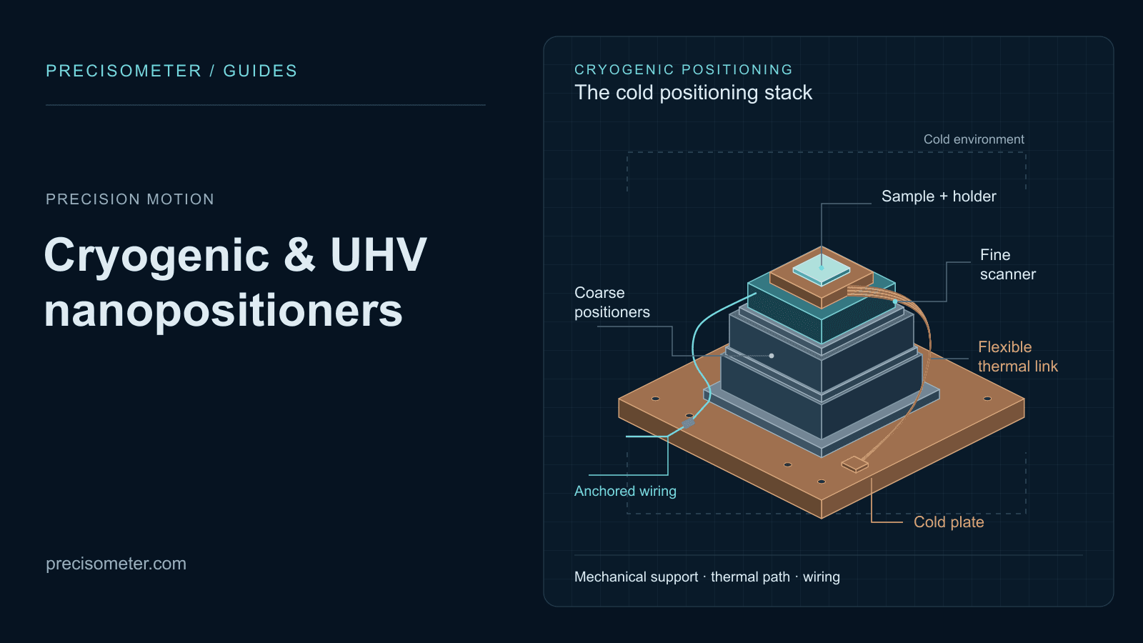
NV centres, quantum dots and 2D materials all need to find an emitter somewhere on a chip and then scan a few tens of micrometres around it. Stick-slip wins the coarse axis because it dissipates power only while moving and locks by friction when it stops — a stage that must be energised to hold position is a permanent heat load on your cold finger.

Cryogenic and UHV selection

Fibre alignment and photonic IC testing

Stick-slip coarse + flexure fine, 3 to 6 axes

20 mm capture, 100 µm fine, nm resolution

Coupling into a waveguide is a search over millimetres followed by a peak-hold over nanometres. The coarse axes need travel and the ability to stay put; the fine axes need continuous, smooth motion for a gradient search. Parallel-kinematic platforms do the same job when you need all six degrees of freedom about one point.

PIC test station guide

Beam steering, adaptive optics and dither

Direct stack, tip/tilt

± 1.5 mrad, ~2 kHz resonance

When the whole job is bandwidth, take the mechanism away. A stack pushing directly on a mirror gives the highest resonance in the catalogue, and a lock-in dither or a beam-stabilisation loop cares about nothing else. Travel is tiny, and for steering a beam that is all you ever needed.

Mirror mounts and steering

Whole-slide and wafer-scale scanning

Stick-slip with optical encoders

100 × 100 mm travel, 10 nm resolution

Travel of this order rules out every analogue architecture immediately. What makes it work is the encoder rather than the motor: the open-loop step of a stick-slip drive is neither repeatable nor linear, so the scale is what turns accumulated steps into a coordinate you can return to.

Long-travel piezo stages

UHV, synchrotron and electron-microscope manipulators

Stick-slip, vacuum and non-magnetic builds

mm travel, bakeable, titanium construction

No lubricants, no outgassing, no motors near the beam, and often no ferromagnetic material at all. A stick-slip drive is a piezo, a friction surface and a spring, which is about as compatible with those constraints as a motion mechanism can be. Look for HV, UHV and NM suffixes rather than a different stage.

Vacuum and cryogenic stages

Metrology frames and high-force positioning

Direct stack or walking drive

100+ N, tens of N/µm, sub-nm

Nanoindentation, wafer chucks, interferometer references and lithography stages need stiffness first — an axis that does not deflect when the world pushes on it. Amplification is the wrong direction here, since a lever divides stiffness by the square of its ratio. Walking drives exist precisely to keep that stiffness while still travelling centimetres.

Motion control range

Screening, autofocus and industrial alignment

Ultrasonic resonant motor

100–300 mm/s, 30–100 nm closed loop

When throughput is the specification and 50 nm is plenty, a resonant motor moves two orders of magnitude faster than anything else in this guide. It runs a mechanical resonance continuously, so it heats and it wears — acceptable on a production line, disqualifying in a cryostat.

Find a stage by specification

Where this goes wrong

Five specification errors worth avoiding.

Reading the open-loop step size as a resolution

A stick-slip datasheet may quote a 50 nm step. That is an average of a stochastic process that varies with load, direction, temperature and the state of the friction surface, and it does not accumulate into a position. Resolution on these stages comes from the encoder, which is why the same mechanism is sold at 50 nm, 2 nm and 0.5 nm classes with identical motors.

Buying travel from a lever and expecting the speed to survive

Amplification multiplies travel by the ratio, divides stiffness by its square and divides resonance by roughly the ratio. A 10x mechanism that turns 20 µm into 160 µm has also turned a several-kilohertz actuator into a few-hundred-hertz one — before your payload lands on it.

Asking an analogue actuator to hold position

A stack or flexure only stays extended while it is energised. Over a long hold you get creep, amplifier drift and a continuous power draw. If the axis is set once and left, a self-locking stepping drive holds it mechanically at zero power and zero dissipation, which matters enormously in a cryostat and is simply tidier everywhere else.

Putting the fine axis under the coarse one

Stack order decides what your resolution is worth. A fine scanner carried by a coarse stage inherits every angular error of that stage, multiplied by the offset to your sample — which is usually a larger number than the scanner error you paid to eliminate.

How Abbe error is calculated

Ignoring the environment until after the model number

Ultrasonic motors dissipate at resonance and have nowhere to send that heat in vacuum. Analogue actuators lose roughly half their stroke at 4 K. Non-magnetic builds change the materials, not just the label. Environment eliminates architectures faster than any performance requirement, so apply it first.

From the catalogue

Each architecture, as a model number.

Every figure below is taken from the specification of the model named. Read them as illustrations of the mechanism rather than as a shortlist — the point is how differently the same ceramic behaves depending on what is built around it.

MC-Newton.S vs MC-Archimedes.N

The two families, seen from the electronics Two families, two controllers
  • MC-Newton: 0–75 V, USB 2.0
  • Drives stick-slip Lab, Indus, Mini
  • MC-Archimedes: up to 8 channels
  • −20 to 150 V, capacitive or strain gauge

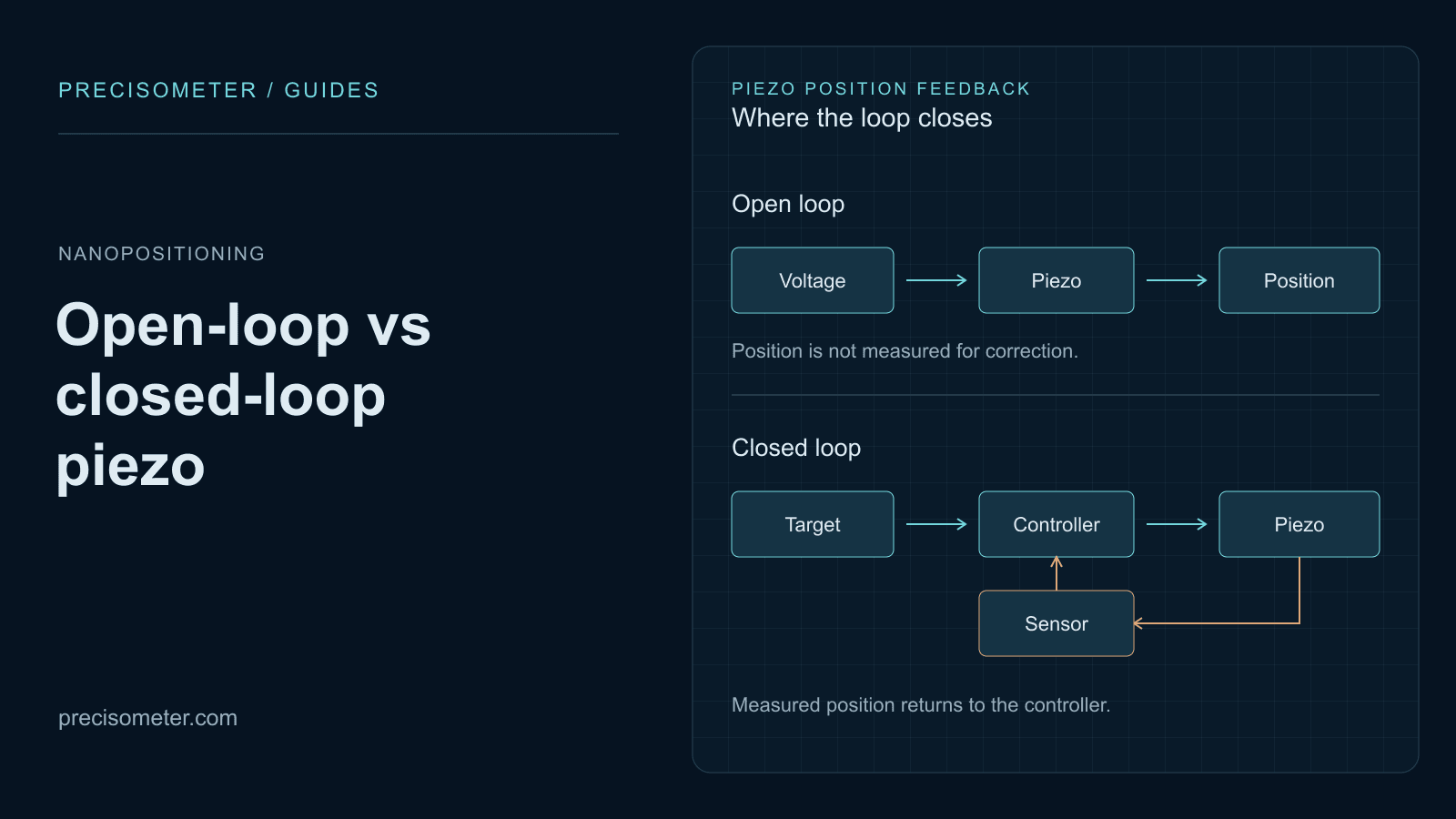
The clearest way to see that these are two different machines is to look at what drives them. The stepping controller generates a sawtooth and counts steps; it has no idea where the stage is without an encoder. The scanner controller generates a smooth analogue voltage over a wider bipolar range and closes a loop around a position sensor. Neither will drive the other kind of stage, so the architecture decision is also a controller decision.

LS35x.Lab

Stick-slip, encoded
  • 20 mm travel
  • 35 × 35 mm footprint
  • 2 nm standard, 0.5 nm .adv
  • 500 g payload

A compact stick-slip linear stage where the encoder does the work: the same mechanism ships as a 50 nm class, a 2 nm class and a 0.5 nm class stage, and only the feedback differs. Note the dynamic range — 20 mm of travel at 2 nm is 10 million to one, which no analogue actuator can approach.

L030.Indus · LS200.Indus

Long-travel stepping
  • 30 mm and 200 mm travel
  • 1–2 kg payload
  • Self-locking drive
  • HV, UHV and NM variants

Two hundred millimetres of piezo travel in an 80 mm wide body, self-locking when the drive is off. This is the range where the question stops being piezo versus piezo and becomes piezo versus a motorised screw stage — the piezo wins on resolution, vacuum compatibility and the absence of a motor, and loses on speed.

X11.mini

Stepping in 11 mm
  • 11 × 11 × 6.5 mm
  • 6 mm travel
  • Sub-1 nm resolution
  • 50 g payload

Six millimetres of travel inside an eleven millimetre cube, which is the argument for stick-slip in one specification. Nothing analogue reaches a fraction of that range at this size, because analogue travel is set by how much ceramic you can fit along the axis.

Carrier.OB100.C

Amplified flexure, closed loop
  • 100 µm Z travel
  • 1 nm closed-loop resolution
  • 250 Hz at 150 g load
  • M25 × 0.75 mount

The flexure architecture doing what it is best at: smooth, friction-free, endlessly repeatable travel over the depth of a specimen. The 250 Hz figure is quoted with a 150 g objective on it rather than unloaded, which is the honest way to specify a scanner and rarer than it should be.

Mirrors.TxTy.0303

Direct stack, tip/tilt
  • ± 1.5 mrad per axis
  • ~2 kHz resonance
  • Closed-loop two-axis
  • HV, UHV and NM variants

What happens when you delete the amplification mechanism: the fastest thing in the piezo catalogue, at a travel that would be useless for positioning a sample and is entirely sufficient for steering a beam. Architecture and application picked each other here.

Scanner35-xy

Flexure scanner, cold
  • 100 × 100 µm at 300 K
  • 60 × 60 µm at 4 K
  • 75 V at 300 K, 180 V at 4 K
  • Friction-free flexure

The analogue derating written into a single datasheet. Cooling costs about 40 % of the stroke and the drive voltage more than doubles to recover what is left, because piezo coefficients fall with temperature. Specify the range you need at your operating temperature, never at 300 K.

Linear25-x · LS-Linear100

Cryogenic stepping
  • 6 mm and 100 mm travel
  • 500 g and 1 kg payload
  • ~150 nm resistive encoder
  • 25 mm and 32 mm bodies

The coarse half of a cold stack. Both hold position by friction with the drive off, so they add nothing to the heat load once they stop — the property that makes stick-slip the default cryogenic mechanism, ahead of any resolution argument.

Free6D.3-2.150

Parallel kinematics
  • ± 10 mm X/Y, ± 5 mm Z
  • ± 10° Tx/Ty, ± 20° Rz
  • 20 nm incremental motion
  • 1 kg payload

Six stepping struts instead of six stacked axes. The virtual pivot can be placed anywhere, including inside your sample, and the errors do not accumulate through a tower of stages — at the cost of a coupled coordinate transformation and a controller that has to solve it in real time.

Most real axes end up as two mechanisms rather than one. Tell us the travel, the smallest move that matters, the payload and the environment, and we will tell you whether that is one stage or a stack — and which controller each half needs.

Putting it together

The mechanism is half the axis.

Choosing the mechanism in practice

Each architecture lives in a different part of the catalogue, and the controller comes with it. These are the pages to compare against once you know which family you need.

  • Ambient piezo stages

    Stick-slip linear, rotary and goniometer stages, flexure scanner modules, objective scanners and the controllers for both families.

  • Cryogenic piezo stages

    Titanium stepping positioners and open-loop or Ultra flexure scanners, with the thermal links a cold stack needs.

  • Piezo stage builder

    Configure a coarse and fine stack together rather than picking two model numbers and hoping they mate.

  • Motion control

    Motorised stages and multi-axis controllers, for the axes where a piezo is the wrong tool entirely.

  • Stage finder

    Filter by travel, resolution, load and environment across every mechanism at once.

One question settles the family faster than any specification: does the axis have to stay where you put it after the power goes off? Yes means a stepping drive. No, and it scans, means analogue.

What sits around the mechanism

The architecture decides what the axis can do. The mounting, the stack order and the thermal path decide how much of that reaches your sample.

  • Manual stages

    For axes aligned once at build time. Cheaper than any drive, and one less thing dissipating in the assembly.

  • Fibre alignment stages

    The canonical coarse-plus-fine application, packaged as an assembly rather than as parts.

  • Optical tables

    Nanometre motion on a structure that drifts by micrometres is a specification you never receive.

  • Mirror mounts

    Where a direct stack or a fine screw actuator turns a static mount into an adjustable one.

  • Full opto-mechanics catalogue

    Everything above, filterable, when you are assembling rather than selecting.

Common questions

The questions that decide the mechanism.

How much travel can a piezo actuator give?

A piezo ceramic strains by roughly 0.1 to 0.15 percent of its length at full field, so a 20 mm stack gives about 20 to 30 µm and nothing you do to the drive electronics changes that. Every architecture beyond the direct stack exists to work around this one number. A flexure amplifier trades force for displacement and reaches a few hundred micrometres; stepping drives accumulate steps and reach hundreds of millimetres, because their travel is no longer set by the strain of the ceramic at all.

What is a stick-slip or inertial piezo drive?

The piezo is driven with a sawtooth. During the slow ramp, static friction makes a slider move with the actuator; during the fast flyback, the actuator retracts quicker than friction can carry the slider, so it slips and stays roughly where it was. Repeat at a few kilohertz and the slider walks along at a few millimetres per second, in steps of tens to hundreds of nanometres. Because the coupling is friction, the mechanism also holds position when the drive is off, and it dissipates power only while it is moving.

What is the actual resolution of a stick-slip positioner?

Open loop it does not have one in any useful sense. The step size is an average that changes with load, direction, temperature and wear, and errors do not cancel, so accumulated steps are not a position. Two things fix this. An encoder makes the position measurable, giving the 1 to 2 nm figures on commercial datasheets, and the same actuator can also be driven in a smooth analogue mode within a single step, which gives sub-nanometre motion over a few hundred nanometres without stepping at all.

Which piezo architectures hold position with the power off?

All the stepping drives do — stick-slip, walking and ultrasonic — because their motion is coupled by friction or by clamping, and both hold when unpowered. None of the analogue architectures do: a stack, a flexure scanner or a tube retracts as soon as the voltage goes away, and while it is energised it creeps and follows amplifier drift. In a cryostat this is decisive, since a stage that must be held electrically is a permanent heat load, whereas a self-locking one costs you nothing once it has stopped.

Why does a flexure amplifier cost bandwidth?

A lever of ratio n multiplies displacement by n and divides force by n, which is just conservation of work. Stiffness, being force per displacement, therefore falls as n squared. Resonant frequency goes as the square root of stiffness over mass, so it drops by roughly a factor of n — and slightly more in practice, because a bigger lever is a heavier one. A 10x amplifier turns a several-kilohertz actuator into a few-hundred-hertz stage before any payload is added.

Should I use one long-travel stage or a coarse and fine stack?

Compare the dynamic range you need — travel divided by the smallest motion you must make — against what one mechanism provides. Analogue actuators sit around 100,000 to one, encoded stepping drives around 10 million to one. Inside those numbers a single stage is simpler, stiffer and cheaper. Outside them, build a stack: a stepping motor for travel, an analogue actuator for resolution. Mount the fine axis on top of the coarse one, keep the work point as close to the guide as you can, and check the Abbe offset before you assume you kept the resolution.

Which architectures work at 4 K, in UHV or in a magnetic field?

Stick-slip is the default for all three: it is a piezo, a friction surface and a spring, with no lubricants, no motor and no ferromagnetic material in titanium builds. Direct stacks and flexure scanners work cold and in vacuum too, but lose roughly half their stroke at 4 K as the piezo coefficients fall, and need drive voltages of 150 V or more to recover part of it. Ultrasonic motors are the outlier — they run a resonance continuously and cannot shed that heat without convection, which rules them out of both vacuum and cryogenic use.

When should I stop using piezo and use a motorised stage?

Roughly when travel passes 50 to 100 mm, when speed matters more than resolution, or when the payload runs into kilograms. A ball-screw stage with a servo motor gives you hundreds of millimetres at tens of millimetres per second for less money, at the price of a motor, lubricants, backlash and magnetic fields near your experiment. The crossover is not sharp, and long-travel piezo stages exist precisely because vacuum, cryogenic and magnetically sensitive systems will pay a great deal to avoid a motor.

Primary sources

Tell us how far and how finely. We will tell you which mechanism.

Travel, smallest useful move, payload, duty cycle and environment are enough to fix the architecture, and usually enough to say whether you are buying one stage or a coarse and fine pair with a controller for each.

  • Mechanism chosen before the model number
  • Coarse and fine sized against each other
  • Environment applied first, not last