Which motion do you need?
Ambient means room-temperature operation. Add any vacuum requirement explicitly so the stage, sensor, cables and connectors can be specified for it.
| Your task | Starting architecture | Explore |
|---|---|---|
| Visit separated regions or make a larger approach | Long-travel piezo motor stage with optical feedback | LS35x.Lab |
| Follow a local XYZ scan trajectory | Flexure-guided scanner with capacitive feedback | S100.XYZ.C |
| Move the focal plane by moving the objective | Axial objective scanner and the correct adapter | Carrier.OB200.C |
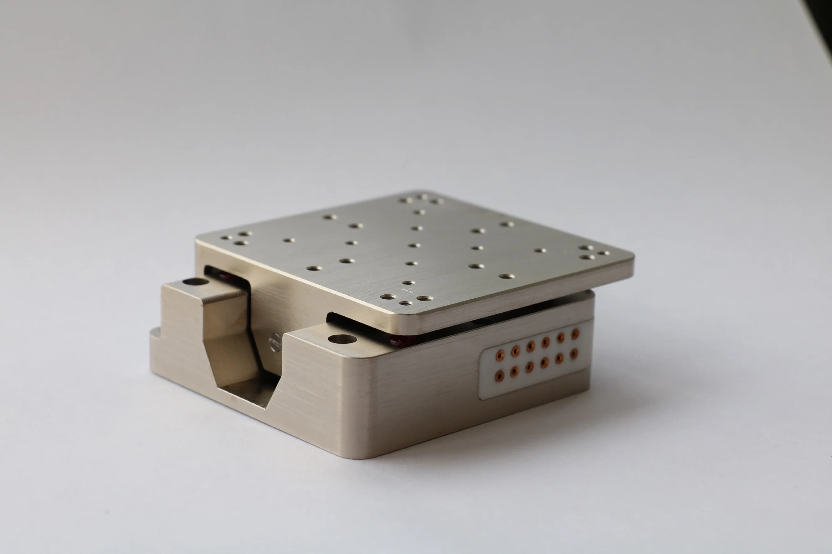
| Adjust translation and angle together | Parallel platform with coordinated axes and a defined pivot | Free6D.3-2.150 |
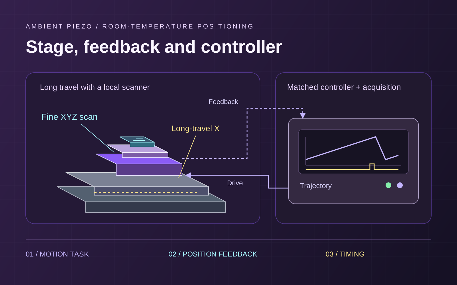
Use a LS35x.Lab to reach separated regions and a S100.XYZ.C for local scans. Include the scanner, holder and cables in the lower stage’s load.
See the microscopy guide for sample versus objective motion, or compare drive architectures.
Four specifications to check
Travel and usable field
Check full stroke versus ± travel, and open-loop versus closed-loop range. Allow room for alignment and drift correction.
Resolution and incremental motion
Encoder resolution describes readout. Minimum incremental motion describes a repeatable small move. Ask for each at the intended load and controller settings.
Repeatability and stability
Specify return direction and tolerance. For a hold, measure relative motion over the acquisition time and bandwidth.
Payload and geometry
Include adapters, upper stages and cable forces. Check orientation, centre of gravity and moment loads as well as mass.
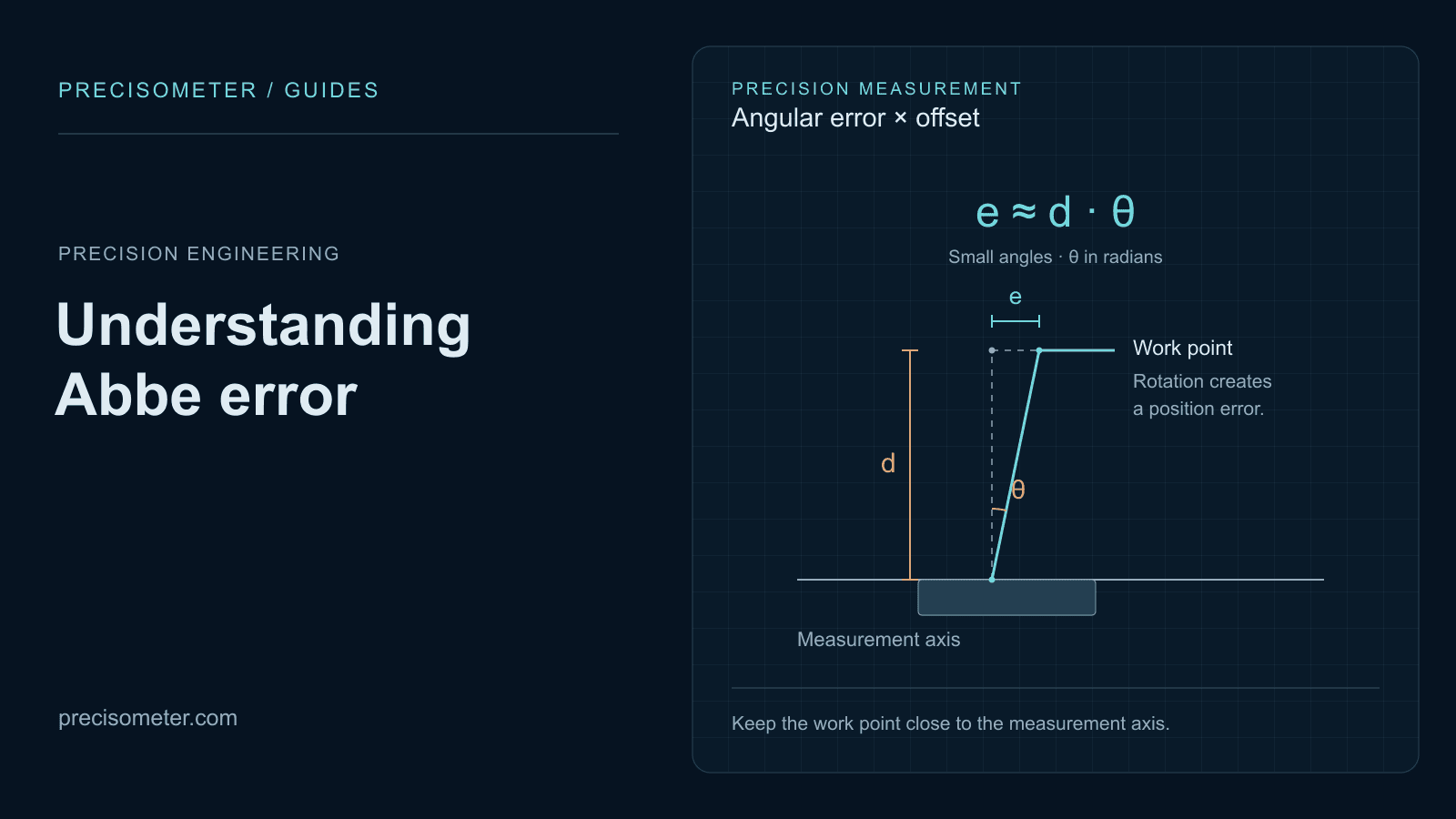
Check these specifications separately. Our Abbe error guide covers offset-and-angle errors. [1]
Free6D.3-2.150 lists ±10 mm X/Y and ±5 mm Z travel. Check the combined workspace at your working pose and pivot; individual maxima do not define a simultaneous six-axis envelope. [4]
Interactive / Scanner waveform budget
Compare scanner current
Compare ideal waveforms at the same capacitance, voltage span and cycle rate. Inputs are assumptions for an analogue scanner, not product ratings or motor stepping waveforms.
Ideal peak current · Raster + flyback
20.0 mA
- Ideal current RMS
- 6.7 mA
- Peak-current-only ceiling
- 10.0 Hz
- Raster forward current
- 2.2 mA
- Raster return duration
- 10.0 ms
Within the assumed peak allowance. Confirm continuous current, peak duration, voltage limits, loaded tracking and thermal limits separately.
| Waveform | Peak current | Current RMS | Current-only ceiling |
|---|---|---|---|
| Sine | 6.3 mA | 4.4 mA | 31.8 Hz |
| Triangle | 4.0 mA | 4.0 mA | 50.0 Hz |
| Raster + flyback | 20.0 mA | 6.7 mA | 10.0 Hz |
Calculation and assumptions
Model: I = C dV/dt. For Vpp and full-cycle frequency f, sine peak = πfCVpp; symmetric triangle = 2fCVpp; raster ramps = fCVpp/D and fCVpp/(1−D). Assumes constant effective capacitance and a symmetric source/sink allowance. RMS is a mathematical load measure, not a substitute for an amplifier’s specified continuous-current definition. The peak-current-only ceiling is not a usable scan-bandwidth rating. Voltage offset, mechanical dynamics, sensor feedback, turnaround smoothing and thermal limits are excluded. Electrical-operation reference.
Allow for flyback
At 90% forward duty, the return covers the same span in one ninth of the time and needs nine times the ideal ramp current.
Use the actual voltage across the piezo, not the low-voltage command signal. Send the waveform, effective capacitance and return timing so we can check continuous current and peak duration. [2]
Match the controller and acquisition
| Stage example | Listed controller family | Discuss with us |
|---|---|---|
| LS35x.Lab | MC-Newton.S | Motor drive, optical feedback, required axes and return sequence. |
| S100.XYZ.C Carrier.OB200.C | MC-Archimedes.N | Scanner channels, sensor configuration, waveform and loaded tuning. |
| Free6D.3-2.150 | MC-Free6D | Coordinated motion, coordinate transforms, pivot and travel limits. |
Confirm controller channels, sensor inputs, firmware and trigger behaviour. Host update rate and feedback sampling rate do not establish the loaded stage’s tracking bandwidth. [3]
For point acquisition, trigger after position error stays within your chosen band for a defined time. For continuous scans, synchronise detector samples with the trajectory and handle flyback blanking.
Carrier.OB200.C lists 480 Hz resonance unloaded and 220 Hz with 150 g. Ask for settling at your load, step size and error band; resonance alone cannot supply that answer.
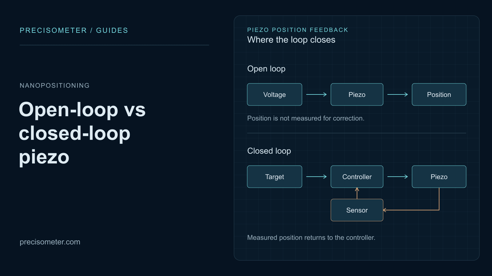
Compare open-loop and closed-loop control for your return, scan and stability requirements.
Compare ambient piezo systems
Choose the motion task, then confirm the exact stage, controller and mounting configuration with us.
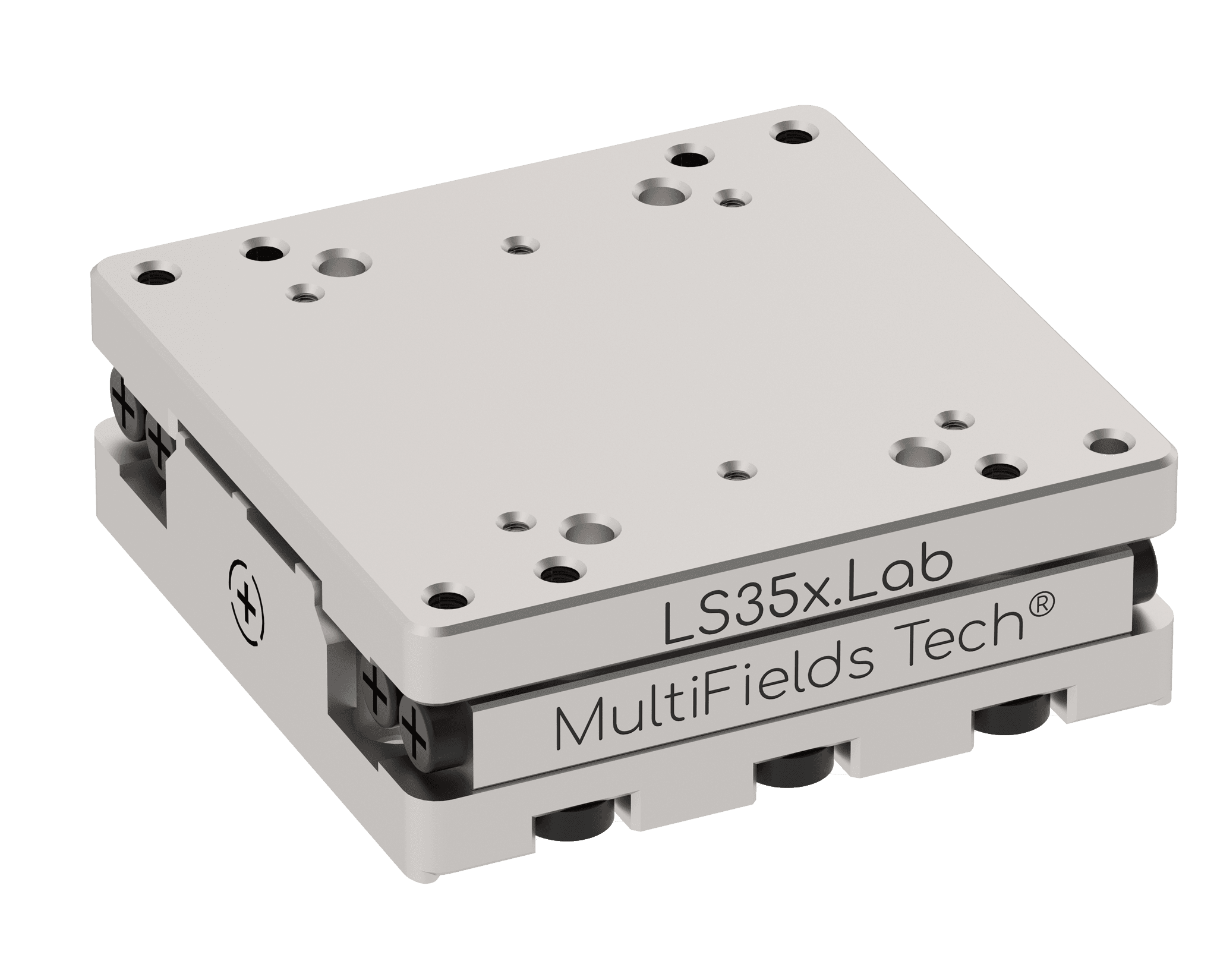
Long-travel positioning
LS35x.Lab
20 mm X travel with optical feedback. Use it to reach regions millimetres apart; add a scanner for local motion.
- Travel range
- 20 mm
- Feedback
- Optical Sensor
- Encoder resolution
- 2 nm
- Controller
- MC-Newton.S series
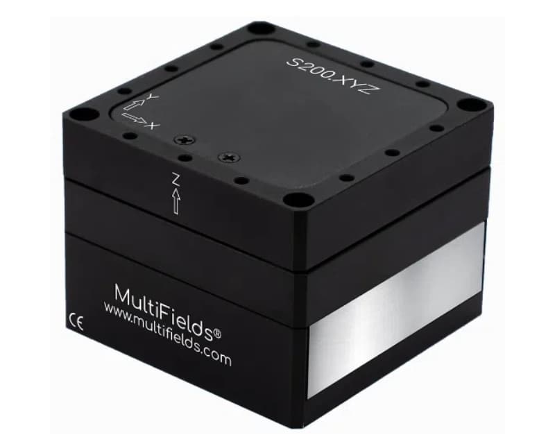
Local XYZ scanning
S100.XYZ.C
A capacitive-feedback XYZ scanner with 100 µm closed-loop travel per axis for local trajectories.
- Closed-loop travel
- 100 × 100 × 100 μm
- Open-loop travel
- 120 × 120 × 120 μm
- Feedback
- Capacitive Sensor
- Controller
- MC-Archimedes.N series
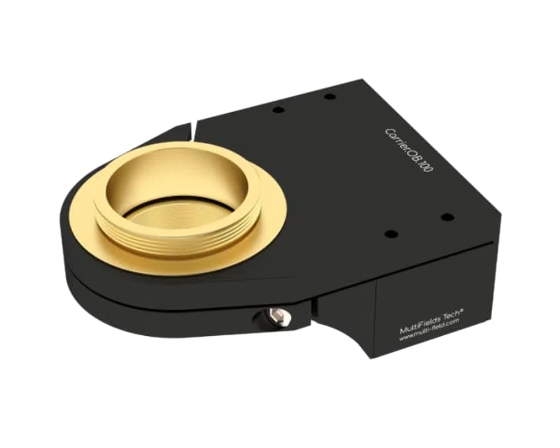
Objective focusing
Carrier.OB200.C
200 µm objective Z travel with capacitive sensing. Confirm objective mass, adapter and turret clearance.
- Travel range
- 200 μm
- Feedback
- Capacitive Sensor
- Resonance with 150 g
- 220 Hz
- Controller
- MC-Archimedes.N series
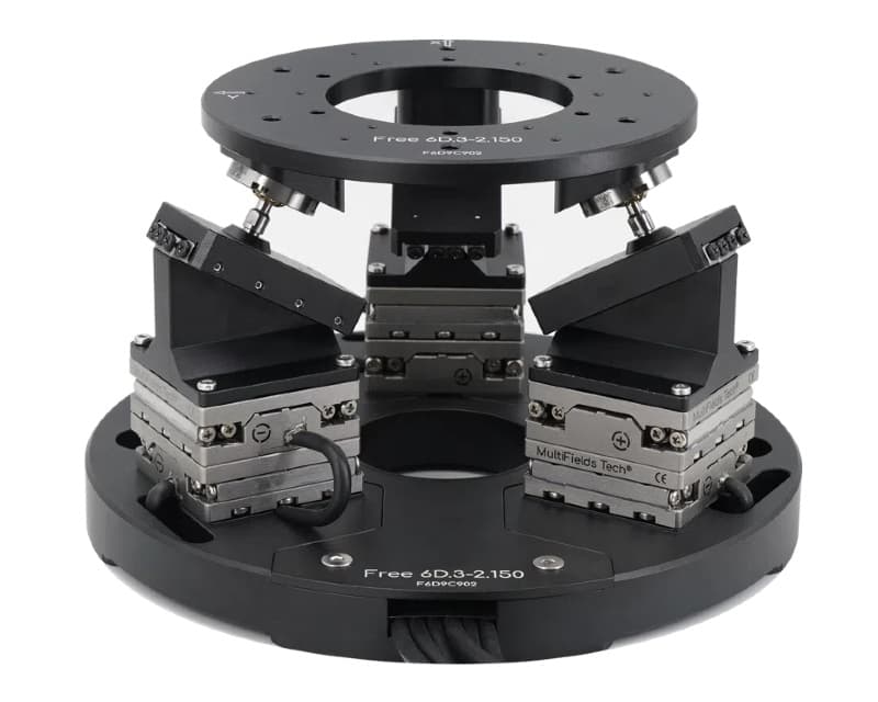
Six-axis alignment
Free6D.3-2.150
Six-axis translation and angular alignment. Specify the working pose, pivot and payload to check the usable workspace.
- Active axes
- X Y Z θX θY θZ
- Translation range per axis
- ±10, ±10, ±5mm
- Feedback
- Optical Sensor
- Controller
- MC-Free6D
Need another footprint or motion range? Browse the catalogue or build an enquiry list.
Test with the real load
- 1Assemble the real load. Fit the holder, cables and specimen or objective. Set limits around the assembled geometry.
- 2Measure the moves you will use. Test small moves, returns and the full scan. Record error and settling against your acceptance band.
- 3Check a complete acquisition cycle. Check motion, trigger, exposure and readout together, including reversals and flyback.
- 4Measure the relevant hold. Measure relative alignment for the full acquisition time. Check supports, airflow, vibration and cable forces.
- 5Save the working configuration. Save load, calibration, waveform, controller settings and cable arrangement with the measurement recipe.
Build your system with Precisometer
Get help choosing a system
Send axes, travel, payload, mounting orientation and available space. Add the scan waveform and acquisition timing, and we’ll help select the stage and controller.
Ambient piezo system questions
What does ambient mean?
Room-temperature operation. Vacuum compatibility is a separate configuration choice for the stage, sensor and wiring.
Motor stage or flexure scanner?
Use a motor stage for longer travel and a flexure scanner for local fine motion. Combine them when you need both scales.
Does 2 nm encoder resolution mean 2 nm accuracy?
No. Resolution, minimum incremental motion, repeatability, accuracy and stability describe different behaviours. Specify the ones your experiment needs.
Why can raster flyback need more current?
Current follows voltage slew rate. At 90% forward duty, the 10% return traverses the same span nine times faster and needs nine times the ideal ramp current.
References and datasheets
Model sheets are linked in the product cards. These references support the selection principles and ideal electrical model.
- [1] Metrology: resolution, noise and minimum incremental motion
Physik Instrumente metrology references distinguish motion measurement, repeatability and resolution.
- [2] Electrical operation of piezo actuators
Capacitive loading, current demand, continuous versus peak amplifier operation and signal-shape considerations.
- [3] MC-Archimedes.N nanopositioning controller
Manufacturer controller compatibility, feedback sampling and host/trigger interfaces.
- [4] Free Series multi-axis parallel stages
Parallel-platform coordinates, per-axis travel and configuration choices.
- [5] Lab Series piezo motion stages
Long-travel motion, optical feedback and configuration-dependent positioning specifications.