See the spatial distribution
Inspect two-dimensional intensity maps, three-dimensional beam profiles and transverse intensity sections to assess spot shape and alignment.
Laser beam measurement
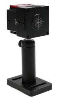
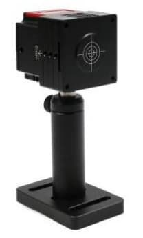
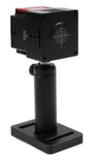
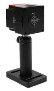
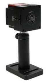
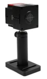
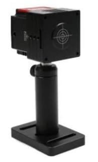
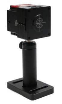
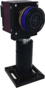
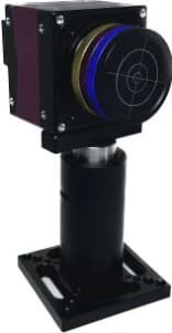
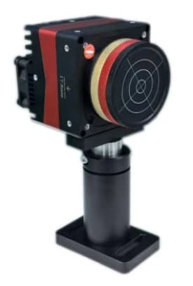
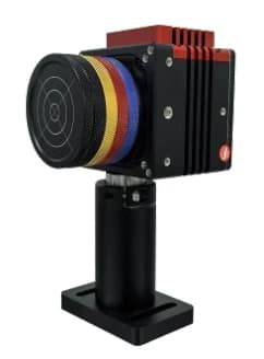
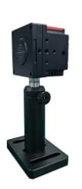
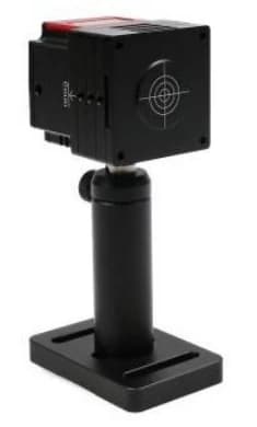
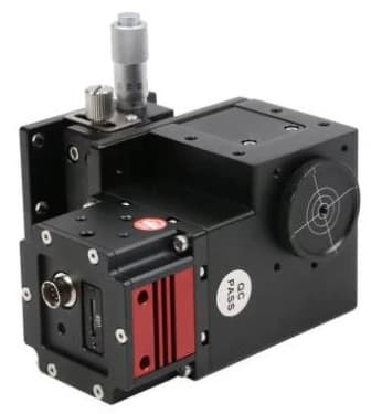
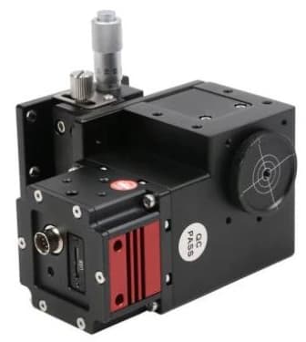
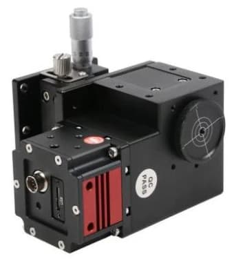
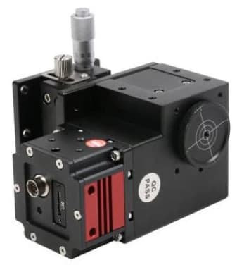
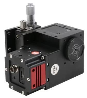
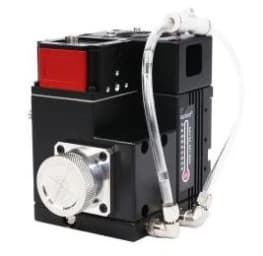
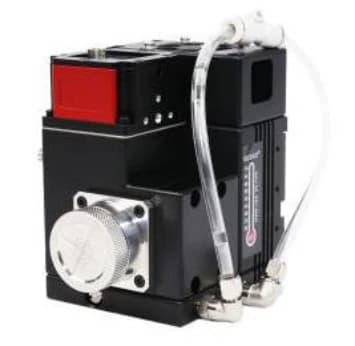
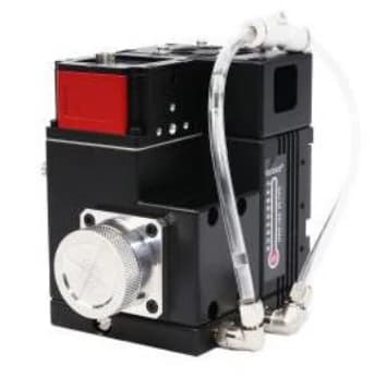
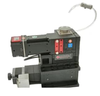
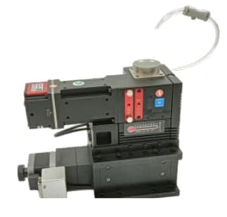
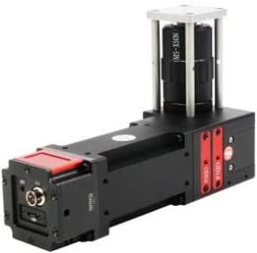
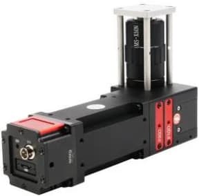
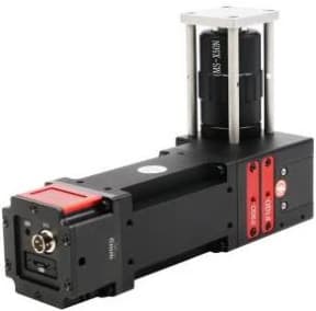
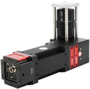
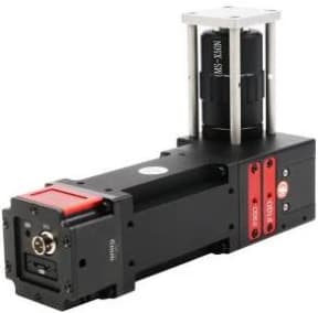
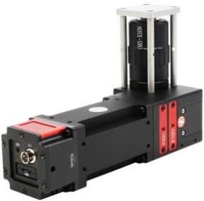
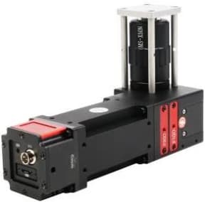
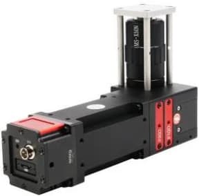
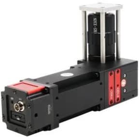
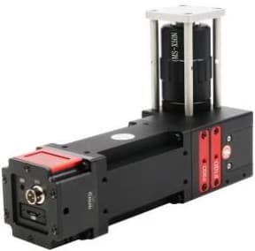
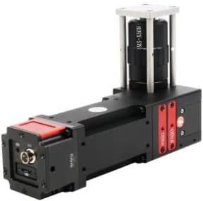
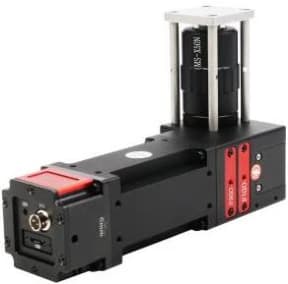
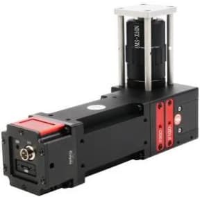
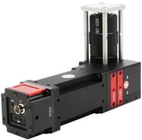
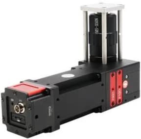
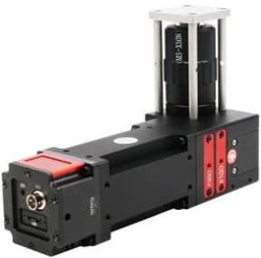
Compare 49 beam profilers across basic, infrared, medium-power, high-power and microfocus series. Explore product photos, beam-analysis examples, mechanical drawings and model-specific specifications with downloadable datasheets.
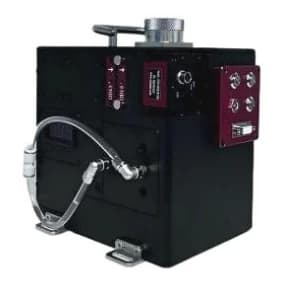
Compare the actual configurations
Every model links to full specifications, measurement conditions, mechanical drawings and its own datasheet. Ratings belong to the selected configuration. Rows marked for confirmation have a documented specification discrepancy.
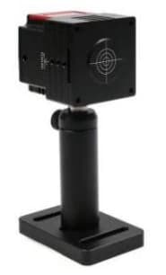
15 models
Direct camera profiling for UV, visible and near-infrared beams, with model-specific sensors, shutters and attenuation.
Select a model for complete specifications, operating conditions and mechanical drawings. Scroll horizontally on smaller screens.
| Model | Spectral range | Spot detection range | Power and conditions | Datasheet |
|---|---|---|---|---|
| CN0204VIS-B | 340-1100 nm | 22 μm-4.3 mm | 1 W | Datasheet |
| CN0204VIS-NIR-B | 340-1100 nm, 1100-1350 nm | 22 μm-4.3 mm | 1 W | Datasheet |
| CD0307VIS-B | 340-1100 nm | 34.5 μm-7.1 mm | 1 W | Datasheet |
| CD0307UV-B | 190-340 nm, 340-1100 nm | 34.5 μm-7.1 mm | 1 W | Datasheet |
| CN0307VIS-B | 340-1100 nm | 34.5 μm-7.1 mm | 1 W | Datasheet |
| CN0307UV-B | 190-340 nm, 340-1100 nm | 34.5 μm-7.1 mm | 1 W | Datasheet |
| CN0310VIS-B | 340-1100 nm | 32 μm-9.8 mm | 1 W | Datasheet |
| CN0310VIS-NIR-B | 340-1100 nm, 1100-1350 | 32 μm-9.8 mm | 1 W | Datasheet |
| CN0511VIS-B | 340-1100 nm | 55 μm-11.3 mm | 1 W | Datasheet |
| CN0511UV-B | 190-340 nm, 340-1100 nm | 55 μm-11.3 mm | 1 W | Datasheet |
| CN0511VIS-NIR-B | 340-1100 nm, 1100-1350 nm | 55 μm-11.3 mm | 1 W | Datasheet |
| CN0512VIS-B | 340-1100 nm | 50 μm-12.8 mm | 1 W | Datasheet |
| CN0615VIS-B | 340-1100 nm | 64 μm-15.8 mm | 1 W | Datasheet |
| CN0615VIS-NIR-B | 340-1100 nm, 1100-1350 nm | 64 μm-15.8 mm | 1 W | Datasheet |
| CN0622VIS-B | 340-1000 nm | 64 μm-22.4 mm | 1 W | Datasheet |
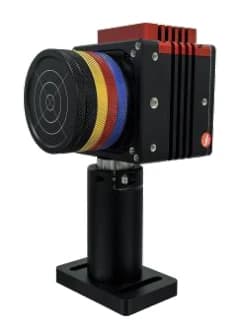
4 models
Infrared and extended-response configurations. Match the exact spectral band, camera technology and power limit.
Select a model for complete specifications, operating conditions and mechanical drawings. Scroll horizontally on smaller screens.
| Model | Spectral range | Spot detection range | Power and conditions | Datasheet |
|---|---|---|---|---|
| CS1507NIR-GB | 900-1700 nm | 150 μm-7.68 mm; TEM00 limit: 4.7 mm | 0.5 W | Datasheet |
| CS1507NIR-B | 1250-2100 nm | 150 μm-7.68 mm | 0.1 W | Datasheet |
| CN0505VIS-NIR-B | 350-1100 nm/1100-1750 nm | 50 μm-5.1 mm(TEM00); TEM00 limit: 3.6 mm | 1 W | Datasheet |
| CN0505NIR-B | 900-1750 nm | 50 μm-5.1 mm | 1 W | Datasheet |
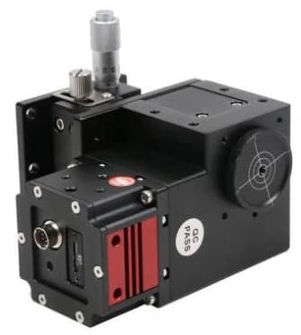
6 models
Integrated attenuation for power levels up to 50 W. Observe the individual time limits and the lower 10 W limit documented for the UV configuration.
Select a model for complete specifications, operating conditions and mechanical drawings. Scroll horizontally on smaller screens.
| Model | Spectral range | Spot detection range | Power and conditions | Datasheet |
|---|---|---|---|---|
| CN0204VIS-M | 340-1100 nm | 22 μm to 4.3 mm; TEM00 limit: 2.9 mm | 50 W | Datasheet |
| CD0307UV-MConfiguration confirmation required | 190-340 nm | 35 μm to 7.1 mm; TEM00 limit: 4.7 mm | 10 W | Datasheet |
| CN0307VIS-M | 340-1100 nm | 35 μm to 7.1 mm; TEM00 limit: 4.7 mm | 50 W | Datasheet |
| CN0310VIS-M | 340-1100 nm | 32 μm to 9.8 mm; TEM00 limit: 6.5 mm | 50 W | Datasheet |
| CN0615VIS-MConfiguration confirmation required | 340-1100 nm | 32 μm to 15 mm; TEM00 limit: 11 mm | 50 W | Datasheet |
| CN0615VIS-NIR-MConfiguration confirmation required | 340-1100 nm/ 1100-1350 nm | 32 μm to 15 mm; TEM00 limit: 11 mm | 50 W | Datasheet |
7 models
Conditioned measurements up to 1000 W. Wavelength, spot size, cooling and operating time determine the usable rating.
Select a model for complete specifications, operating conditions and mechanical drawings. Scroll horizontally on smaller screens.
| Model | Spectral range | Spot detection range | Power and conditions | Datasheet |
|---|---|---|---|---|
| CN0104VIS-W300 | 340-1080 nm | 20 μm to 4 mm; TEM00 limit: 2.6 mm | 300 W, focused spot ≥50 μm, CW | Datasheet |
| CN0310VIS-W300 | 340-1080 nm | 50 μm to 9.8 mm; TEM00 limit: 6.5 mm | 200 W, focused spot ≥50 μm, CW | Datasheet |
| CN0104NIR-W500Configuration confirmation required | 1030-1080 nm | 20 μm to 4 mm; TEM00 limit: 2.6 mm | 200 W, Converge Light≥20 μm, CW 300 W, Converge Light≥50 μm, CW 500 W, Converge Light≥100 μm, CW | Datasheet |
| CN0310NIR-W500 | 1030-1080 nm | 50 μm to 9.8 mm; TEM00 limit: 6.5 mm | 300 W, Converge Light≥50 μm, CW 500 W, Converge Light≥100 μm, CW | Datasheet |
| CN0104NIR-W500-AZ20L | 1030-1080 nm | 20 μm to 4 mm; TEM00 limit: 2.6 mm | 200 W, Converge Light≥20 μm, CW 300 W, Converge Light≥50 μm, CW 500 W, Converge Light≥100 μm, CW | Datasheet |
| CN0310NIR-W500-AZ20L | 1030-1080 nm | 50 μm to 9.8 mm; TEM00 limit: 6.5 mm | 300 W@focusing spot≥50 μm, CW 500 W@focusing spot≥100 μm, CW | Datasheet |
| CN0310NIR-W1000-FA10Y | 1030-1080 nm, Other wavelength bands customizable | 32 μm-5 mm@1/e²(TEM00) | 1000 W water-cooled continuous operation | Datasheet |
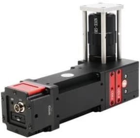
17 models
Magnified focal-spot imaging with 5x, 10x, 20x or 50x configurations and wavelength-specific optical paths.
Select a model for complete specifications, operating conditions and mechanical drawings. Scroll horizontally on smaller screens.
| Model | Spectral range | Spot detection range | Power and conditions | Datasheet |
|---|---|---|---|---|
| CD0307UV-XD | 248-266 nm | 5 μm-0.5 mm | 1 W @ minimum spot size 0.5mJ @ minimum spot size | Datasheet |
| CN0205UV-XUConfiguration confirmation required | 400-800 nm | 5 μm-0.5 mm | 1 W @ minimum spot size | Datasheet |
| CN0307UV-XU | 343-355 nm | 5 μm-0.5 mm | 3 W@ min. focus spot | Datasheet |
| CN0310VIS-XGW05 | 515 nm-532 nm | 10 μm-1 mm | 2.5 W@minimum focal spot | Datasheet |
| CN0310VIS-XG | 515 nm-532 nm | 5 μm-0.5 mm | 5 W@minimum focal spot | Datasheet |
| CN0310VIS-XGW | 515 nm-532 nm | 5 μm-0.5 mm | 2.5 W@minimum focal spot | Datasheet |
| CN0310VIS-XGW2 | 515 nm-532 nm | 2.5 μm-0.25 mm | 2.5 W@minimum focal spot | Datasheet |
| CN0310VIS-XGW5 | 515 nm-532 nm | 1 μm-0.1 mm | 2.5 W@minimum focal spot | Datasheet |
| CN0310NIR-XNW05 | 900-1100 nm | 10 μm-1 mm | 5 W@minimum focal spot | Datasheet |
| CN0310NIR-XN | 900-1100 nm | 5 μm-0.5 mm | 10 W@ min. focus spot | Datasheet |
| CN0310NIR-XNW | 900-1100 nm | 5 μm-0.5 mm | 5 W@minimum focal spot | Datasheet |
| CN0310NIR-XNW2 | 900-1100 nm | 2.5 μm-0.25 mm | 5 W@minimum focal spot | Datasheet |
| CN0310NIR-XNW5 | 900-1100 nm | 2 μm-0.1 mm | 5 W@minimum focal spot | Datasheet |
| CN0310VIS-XVW05 | 400-800 nm | 10 μm-1 mm | 0.5 W@minimum focal spot | Datasheet |
| CN0310VIS-XVW | 400-800 nm | 5 μm-0.5 mm | 0.5 W@minimum focal spot | Datasheet |
| CN0310VIS-XVW2 | 400-800 nm | 2.5 μm-0.25 mm | 0.5 W@minimum focal spot | Datasheet |
| CN0310VIS-XVW5 | 400-800 nm | 1 μm-0.1 mm | 0.5 W@minimum focal spot | Datasheet |
From image to measurement
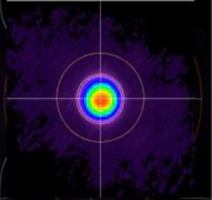
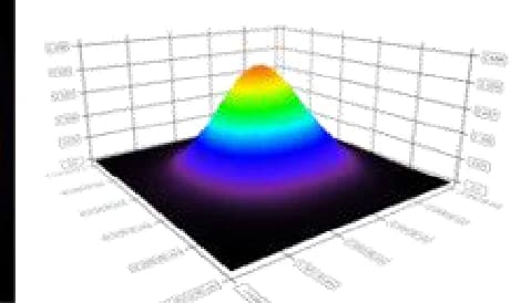
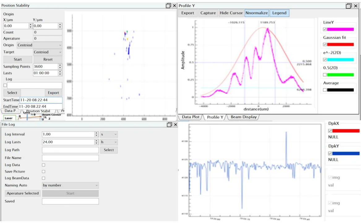
Illustrative software output. Results, analysis functions and acquisition rates depend on the selected hardware, software and beam conditions.
Inspect two-dimensional intensity maps, three-dimensional beam profiles and transverse intensity sections to assess spot shape and alignment.
Analyse beam diameter, ellipticity and position. Suitable configurations support multi-spot monitoring, image stitching and pointing-stability analysis; acquisition and processing rates are model dependent.
Check exposure, shutter and external-trigger support for your timing requirements. The 1000 W system specifies beam analysis and optional automatic M² workflows; these capabilities require the stated software and hardware configuration.
01
Choose the exact detection band and the attenuation or window configuration. A family range combines different models; it does not make every instrument broadband.
02
Compare the minimum detectable spot with the maximum usable beam size. Sensor pixel size, optical magnification and quoted measurement resolution describe different quantities. Gaussian TEM00 limits may be smaller than the sensor aperture.
03
Read total power, irradiance and pulse-energy-density limits together. Include pulse duration, repetition rate, beam diameter, cooling and the permitted measurement time. Attenuation conditions belong to the quoted limit.
04
Match USB or GigE, trigger support, software requirements and beam-entry geometry. Divergence needs measurements at known axial positions; automated M² analysis requires the appropriate scan hardware and software configuration.
Technical FAQ
No. The rating depends on wavelength, beam diameter, attenuation, cooling and operating time. For example, the 500 W configurations distinguish 200 W, 300 W and 500 W operation by focused-spot size and measurement time. The 1000 W model specifies continuous operation with water cooling.
Not always. Several models give a smaller TEM00 or 1/e² beam limit than the geometric sensor range. Read the model footnotes and central-incidence conditions alongside the main table.
A single profile gives the transverse distribution at one plane. Divergence and M² require measurements along the propagation axis, suitable optics and a defined analysis method. Confirm the translation, attenuation and software configuration for that workflow.
Most listed models specify Windows 10 or 11, 64-bit, with MS Office or WPS, at least 8 GB RAM and a processor of at least 2.5 GHz with four or more cores. USB3.0, GigE, 10GigE and trigger availability vary by model; use its exact specification.
Keep the optical, electrical, mechanical and operating specifications together for your configuration.
DatasheetInclude wavelength, beam size, CW or pulsed operation, pulse energy, repetition rate, power, exposure time, cooling and the measurements you need.