Tilt correction after cooldown
Recover sample planarity once differential contraction has tilted the mount.
Opto-Mechanics · Cryogenic Piezo Stages - Goniometers
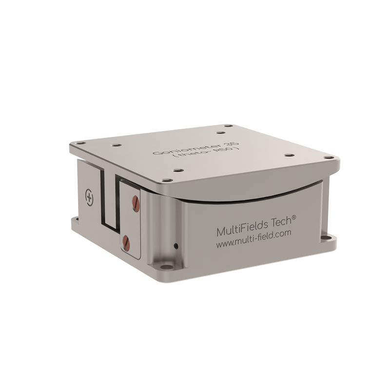
Cryogenic phi goniometer; 25 x 25 mm footprint; 6.0 deg tilt range; 53.5 mm pivot distance above plate; 200 g payload; resistive closed-loop feedback around 0.2-0.5 mdeg resolution.
Datasheet (PDF) ↗CAD Model (STEP) ↗Catalog context
Goniometer25-phi is listed in the Cryogenic Piezo Stages - Goniometers family. The local catalog record provides these first selection fields: Active axes: Rx; Footprint × hight: 25 x 25 x 12.5 mm; Mass: 28 g.
| Active axes | Rx |
|---|---|
| Footprint × hight | 25 x 25 x 12.5 mm |
| Mass | 28 g |
| Work environment | Default:1.4 K~ 400 K, 1e-7 mbar, 35 Tesla |
| Mainbody | Default: Pure Ti |
| Wires | Phosphor Bronze Twisted Paired Wires, 20cm |
| Pin materials | Polyster (glass fiber filled), BeCu |
| Pins number | Drive -2 pins, Sensor- 3 pins |
| Fine Tune Resolution @2 K* | 0.5 u° |
| Step Size (min) @300 K* | 50 u° |
| Travel range | ~6 ° |
| Max. Velocity @300 K | ~1°/s |
| Max. Load | 200 g |
| Dynamic Force | 2.2 N |
| Rotation center to top plate | 53.5 mm |
| Sensor | Resistive Sensor |
| Sensor range | 6 ° |
| Sensor resolution | 0.2 m° |
Application context
Recover sample planarity once differential contraction has tilted the mount.
Stack theta and phi units to steer around a common virtual pivot above the top plate.
Set beam incidence inside a cryostat where there is no room to move the optics instead.
System integration
Use these checks to connect Goniometer25-phi to the surrounding optical, mechanical and control system. Every value shown is taken from this model's own specification record.
Technical FAQ
Fine Tune Resolution @2 K*: 0.5 u° · Step Size (min) @300 K*: 50 u°. Separate travel from resolution and both from repeatability. Repeatability is what an automated sequence actually depends on, and it is the figure most often absent from a headline specification.
Max. Load: 200 g. Check the load rating in the orientation you will use it — a vertical or cantilevered load is a moment, not a mass — and match the base to an M6 pattern on a 25 mm grid or a 1/4"-20 pattern on a 1 inch grid.
Specifying this part
Each unit tilts about a centre that sits a fixed height above its own mounting surface — 41 to 66 mm depending on model. Stacking a theta and a phi unit gives dual-axis tip/tilt about one shared virtual pivot, which is why they are specified in matched pairs.
Stick-slip inertial drives dissipate energy per step and draw no holding current once stopped, so the steady-state load on the mixing chamber is the wiring loom rather than the motor. Anchor the loom at each temperature stage and thermalise the moving body with an FTC copper braid.
Titanium bodies (BeCu on the .ULT variants) and BeCu fasteners throughout, rated for operation to 35 T and down to 30 mK with the .ULT option, at 2 × 10⁻¹¹ mbar with .UHV. A single steel screw substituted at installation is enough to compromise a high-field assembly.
Full series comparison, controller pairing and mounting hardware on the cryogenic piezo stages overview, or work through the selection with the configurator.
Model selection
Compare Goniometer25-phi with the closest available models in the Cryogenic Piezo Stages - Goniometers family.
| Selection parameter | Goniometer25-phi (current) | Goniometer25-theta | Goniometer35-phi |
|---|---|---|---|
| Travel / adjustment | ~6 ° | ~6.6 ° | ~10 ° |
| Resolution / sensitivity | 0.5 u° | 0.5 u° | 0.5 u° |
Goniometer25-theta
Cryogenic theta goniometer; 25 x 25 mm footprint; 6.6 deg tilt range; 41 mm pivot distance above plate; 200 g payload; resistive closed-loop feedback around 0.2-0.5 mdeg resolution.
Goniometer35-theta
Cryogenic theta goniometer; 35 x 35 mm footprint; 12.0 deg tilt range; 50 mm pivot distance above plate; 500 g payload; resistive closed-loop feedback around 0.2-0.5 mdeg resolution.
Goniometer35-phi
Cryogenic phi goniometer; 35 x 35 mm footprint; 10.0 deg tilt range; 66 mm pivot distance above plate; 500 g payload; resistive closed-loop feedback around 0.2-0.5 mdeg resolution.
Before you specify
Engineering context for choosing this class of component, with the tradeoffs worked through on real specifications.
 Precision motion
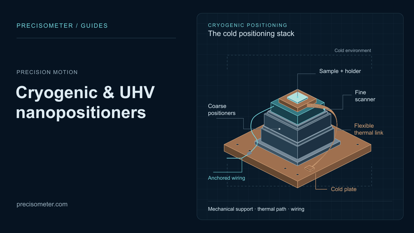
Translate temperature, pressure, travel, payload, feedback, and motion requirements into a defensible cryogenic-stage shortlist.
Open guide Precision motion
The practical companion to the selection guide: a requirements worksheet, coarse and fine stage pairing, mechanical stack order, thermal anchoring, the wiring chain to the controller, vacuum and field checks, a commissioning sequence, and three worked configurations.
Open guide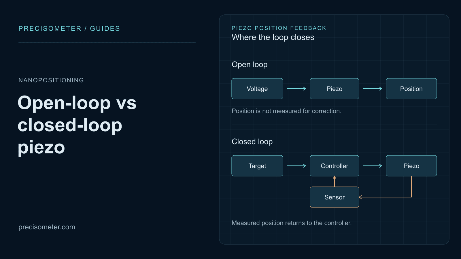 Nanopositioning
Why an open-loop piezo is wrong by 15 % of its travel, how creep grows with the logarithm of hold time, what strain-gauge and capacitive feedback actually fix — and the bandwidth and sensor noise a servo costs you in return.
Open guide