Opto-Mechanics · Cryogenic Piezo Stages - Goniometers
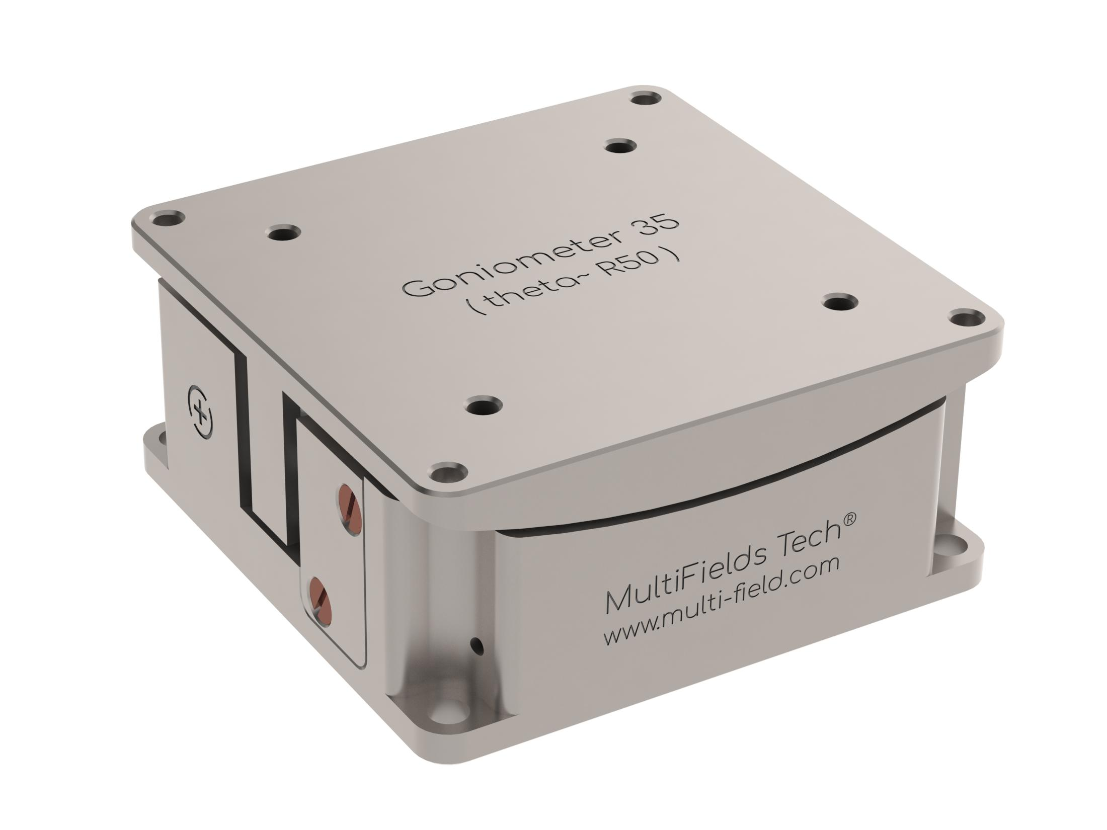
Goniometer35-theta
Cryogenic theta goniometer; 35 x 35 mm footprint; 12.0 deg tilt range; 50 mm pivot distance above plate; 500 g payload; resistive closed-loop feedback around 0.2-0.5 mdeg resolution.
Datasheet (PDF) ↗CAD Model (STEP) ↗Specifications
| Active axes | Rx |
|---|---|
| Footprint × hight | 35 x 35 x 16 mm |
| Mass | 70 g |
| Work environment | Default:1.4 K~ 400 K, 1e-7 mbar, 35 Tesla |
| Mainbody | Default: Pure Ti |
| Wires | Phosphor Bronze Twisted Paired Wires, 20cm |
| Pin materials | Polyster (glass fiber filled), BeCu |
| Pins number | Drive -2 pins, Sensor- 3 pins |
| Fine Tune Resolution @2 K* | 0.5 u° |
| Step Size (min) @300 K* | 50 u° |
| Travel range | ~12 ° |
| Max. Velocity @300 K | ~1°/s |
| Max. Load | 500 g |
| Dynamic Force | 3 N |
| Rotation center to top plate | 50 mm |
| Sensor | Resistive Sensor |
| Sensor range | 12 ° |
| Sensor resolution | 0.5 m° |
Applications
Tilt correction after cooldown
Recover sample planarity once differential contraction has tilted the mount.
Dual-axis tip/tilt
Stack theta and phi units to steer around a common virtual pivot above the top plate.
Incidence angle in confined geometry
Set beam incidence inside a cryostat where there is no room to move the optics instead.
Specifying this part
What this model has to survive, and what it needs around it
Fixed pivot above the top plate
Each unit tilts about a centre that sits a fixed height above its own mounting surface — 41 to 66 mm depending on model. Stacking a theta and a phi unit gives dual-axis tip/tilt about one shared virtual pivot, which is why they are specified in matched pairs.
Heat load at the cold plate
Stick-slip inertial drives dissipate energy per step and draw no holding current once stopped, so the steady-state load on the mixing chamber is the wiring loom rather than the motor. Anchor the loom at each temperature stage and thermalise the moving body with an FTC copper braid.
Non-magnetic construction
Titanium bodies and BeCu fasteners throughout, rated for operation to 35 T and down to 30 mK with the .ULT option, at 2 × 10⁻¹¹ mbar with .UHV. A single steel screw substituted at installation is enough to compromise a high-field assembly.
Full series comparison, controller pairing and mounting hardware on the cryogenic piezo stages overview, or work through the selection with the configurator.
Related products
Goniometer25-theta
Cryogenic theta goniometer; 25 x 25 mm footprint; 6.6 deg tilt range; 41 mm pivot distance above plate; 200 g payload; resistive closed-loop feedback around 0.2-0.5 mdeg resolution.
Goniometer25-phi
Cryogenic phi goniometer; 25 x 25 mm footprint; 6.0 deg tilt range; 53.5 mm pivot distance above plate; 200 g payload; resistive closed-loop feedback around 0.2-0.5 mdeg resolution.
Goniometer35-phi
Cryogenic phi goniometer; 35 x 35 mm footprint; 10.0 deg tilt range; 66 mm pivot distance above plate; 500 g payload; resistive closed-loop feedback around 0.2-0.5 mdeg resolution.

