Opto-Mechanics · Cryogenic Piezo Stages - Closed-loop Ultra scanners
Scanner25-z.Ultra.UHV
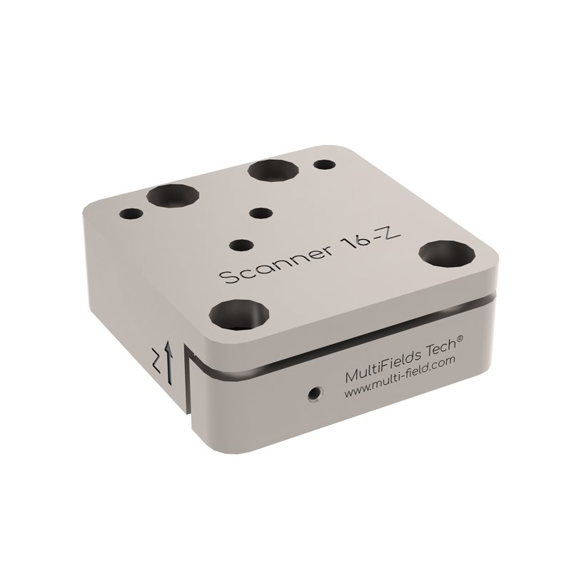
Closed-loop Ultra Z-axis scanner; 25 x 25 x 10.5 mm body; 55 um range per axis at 300 K, 30 um at 4 K; 250 g payload; integrated capacitive displacement sensor, 0.5 nm resolution, ~0.1 % linearity, <5 nm repeatability; max. 75 V @300 K / 150 V @4 K; ultra-high-vacuum UHV environment grade; use with MC-ArchimedesLT.03.Ultra controller.
Datasheet (PDF) ↗CAD Model (STEP) ↗Cataloguscontext
De plaats van Scanner25-z.Ultra.UHV in het assortiment
Scanner25-z.Ultra.UHV staat vermeld binnen de familie Cryogenic Piezo Stages - Closed-loop Ultra scanners. Het lokale catalogusrecord bevat als eerste selectievelden: Active axes: Z; Footprint × hight: 25 x 25 x 10.5 mm; Mass: 80 g.
Specifications
| Active axes | Z |
|---|---|
| Footprint × hight | 25 x 25 x 10.5 mm |
| Mass | 80 g |
| Work Environment | Default: 1.4 K~ 400 K, 1e-7 mbar, 35 Tesla |
| Option 1 - 30 mK | .ULT / .UHV.ULT |
| Option 2 - 2e-11 mbar | .UHV / .UHV.ULT |
| Mainbody | Default: Pure Ti, ULT: BeCu |
| Wires | Twisted paired wire & triax cable |
| Connectors | 2 head pins + 1 triax connector (for each dimension) |
| Travel range | @300 K: 55 um; @4 K: 30 um |
| Drive Voltage | Max. 75 V @300 K, Max. 150 V @4 K |
| Max. Load | 250 g |
| Capacitance @300 K | 7 uF |
| Sensor | Capacitive displacement sensor |
| Resolution | 0.5 nm |
| Linearity error | Typical ~0.1 % |
| Repeatibility | <5 nm |
Toepassingen
Kwantitatieve beeldvorming op basistemperatuur
Capacitieve terugkoppeling koppelt beeldpixels aan werkelijke afstanden in plaats van aan aangelegde spanning.
Cryogene AFM- en STM-raster
Levert lineaire, driftgecorrigeerde scan onder een probekop die onder 4 K werkt.
Herhaalde metingen op dezelfde plek
Keer terug naar dezelfde coördinaat over thermische cycli en lange meetcampagnes heen.
Specifying this part
What this model has to survive, and what it needs around it
What the capacitive loop buys you
An integrated capacitive displacement sensor closes the loop at 0.5 nm and lets the controller compensate thermal drift, piezoelectric creep and self-heating actively. Worth the extra wiring only if the measurement holds position for hours; if the sample is re-found optically each run, open-loop costs less heat.
Reading the HV / UHV / ULT suffixes
The suffix sets the environmental preparation, not the mechanics: HV, UHV, ULT and UHV.ULT variants differ in materials, cabling and bake compatibility. Match it to the chamber the stage will live in — the mechanical specification is identical across them.
Heat load at the cold plate
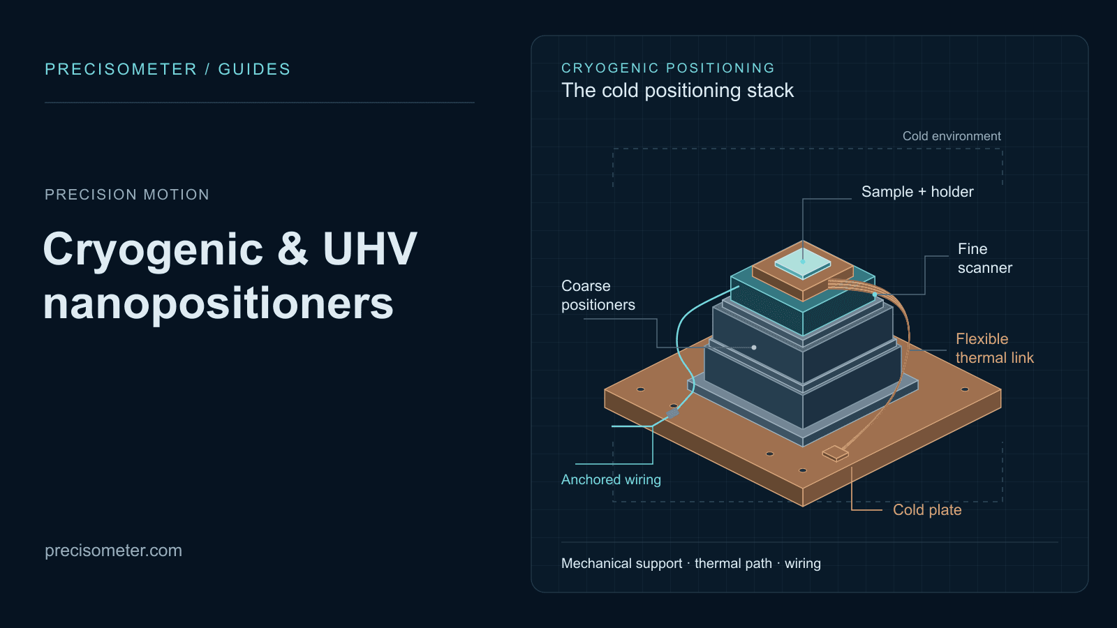
Stick-slip inertial drives dissipate energy per step and draw no holding current once stopped, so the steady-state load on the mixing chamber is the wiring loom rather than the motor. Anchor the loom at each temperature stage and thermalise the moving body with an FTC copper braid.
Non-magnetic construction
Titanium bodies (BeCu on the .ULT variants) and BeCu fasteners throughout, rated for operation to 35 T and down to 30 mK with the .ULT option, at 2 × 10⁻¹¹ mbar with .UHV. A single steel screw substituted at installation is enough to compromise a high-field assembly.
Full series comparison, controller pairing and mounting hardware on the cryogenic piezo stages overview, or work through the selection with the configurator.
Related products
Scanner25-x.Ultra
Closed-loop Ultra X-axis scanner; 25 x 25 x 10.5 mm body; 55 um range per axis at 300 K, 30 um at 4 K; 250 g payload; integrated capacitive displacement sensor, 0.5 nm resolution, ~0.1 % linearity, <5 nm repeatability; max. 75 V @300 K / 150 V @4 K; standard cryogenic environment grade; use with MC-ArchimedesLT.03.Ultra controller.
Scanner25-x.Ultra.HV
Closed-loop Ultra X-axis scanner; 25 x 25 x 10.5 mm body; 55 um range per axis at 300 K, 30 um at 4 K; 250 g payload; integrated capacitive displacement sensor, 0.5 nm resolution, ~0.1 % linearity, <5 nm repeatability; max. 75 V @300 K / 150 V @4 K; high-vacuum HV environment grade; use with MC-ArchimedesLT.03.Ultra controller.
Scanner25-x.Ultra.UHV
Closed-loop Ultra X-axis scanner; 25 x 25 x 10.5 mm body; 55 um range per axis at 300 K, 30 um at 4 K; 250 g payload; integrated capacitive displacement sensor, 0.5 nm resolution, ~0.1 % linearity, <5 nm repeatability; max. 75 V @300 K / 150 V @4 K; ultra-high-vacuum UHV environment grade; use with MC-ArchimedesLT.03.Ultra controller.
Scanner25-x.Ultra.ULT
Closed-loop Ultra X-axis scanner; 25 x 25 x 10.5 mm body; 55 um range per axis at 300 K, 30 um at 4 K; 250 g payload; integrated capacitive displacement sensor, 0.5 nm resolution, ~0.1 % linearity, <5 nm repeatability; max. 75 V @300 K / 150 V @4 K; ultra-low-temperature ULT grade down to 30 mK; use with MC-ArchimedesLT.03.Ultra controller.