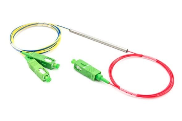
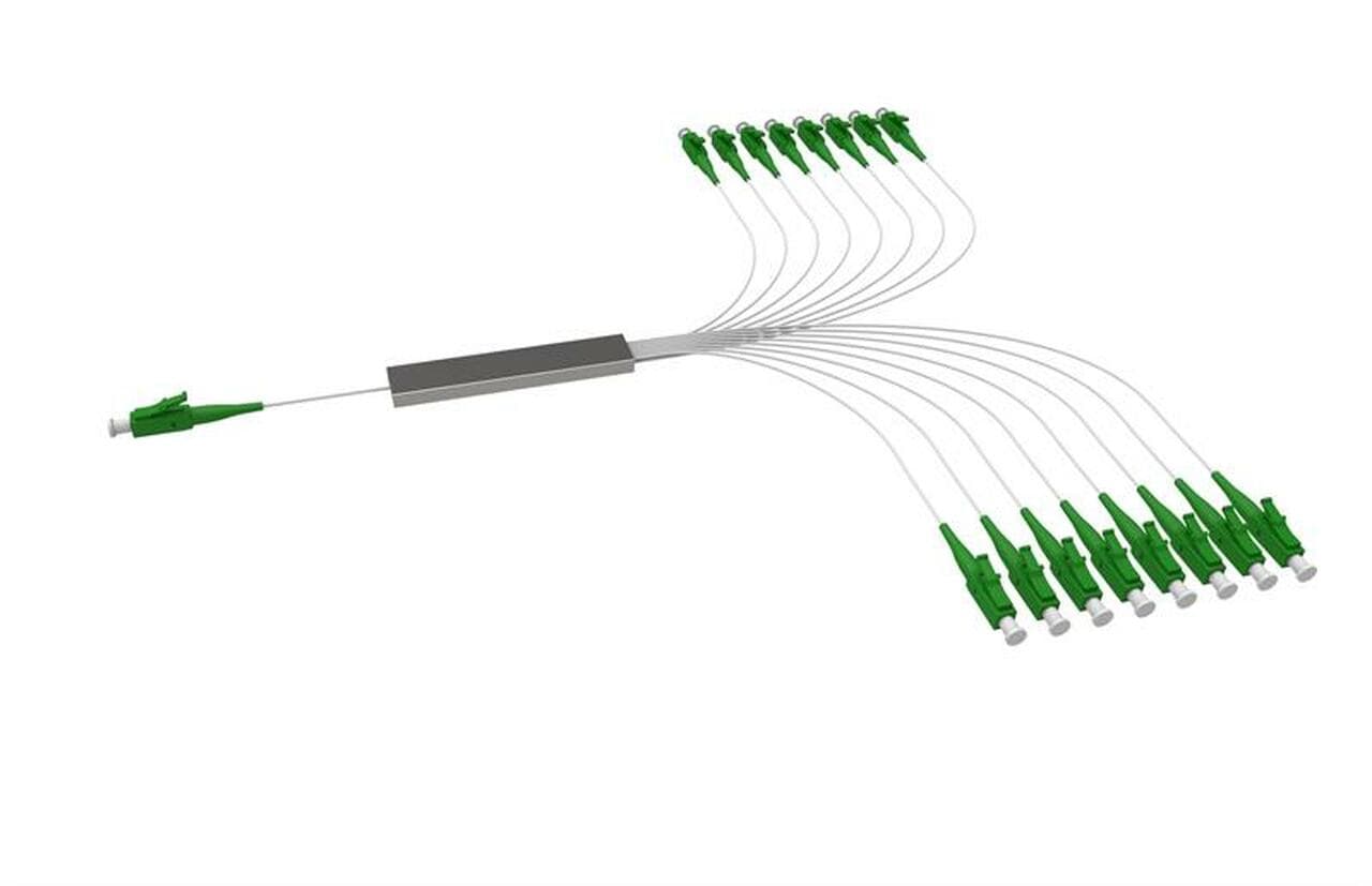
Optical power distribution
Coupling ratio and uniformity set the power delivered to each branch, while excess loss determines total source headroom.
Couplers, Splitters & Combiners
Double Cladding Fiber Fused Coupler/Splitter is a configurable fiber coupler, splitter or combiner in the Couplers, Splitters & Combiners family. The final part number should be released only after the optical, mechanical, electrical and environmental fields below are matched to the intended instrument.
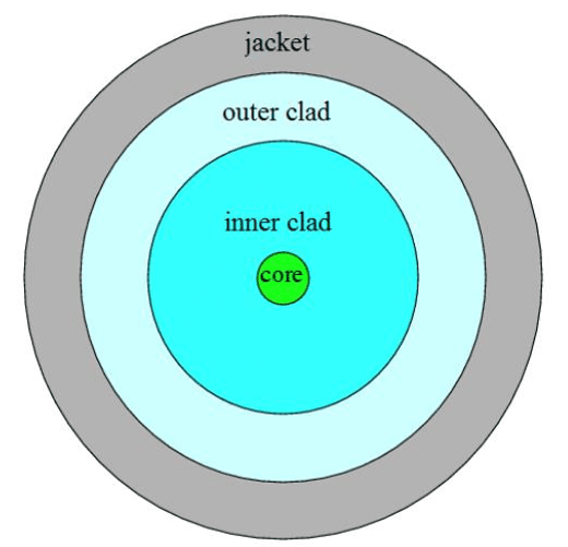
Engineering reference
Double Cladding Fiber Fused Coupler/Splitter is a configurable fiber coupler, splitter or combiner in the Couplers, Splitters & Combiners family. The final part number should be released only after the optical, mechanical, electrical and environmental fields below are matched to the intended instrument.
A fiber coupler redistributes guided optical power between ports. Coupling ratio is only one part of the design: excess loss, uniformity, directivity, fiber mode and polarization behavior determine whether the component preserves the experiment’s optical budget.
The source record contains no configuration table or datasheet. The fields below are therefore procurement requirements to confirm, not claimed values for every option.
Application context
Application guidance is tied to the configured wavelength, fiber interface and optical-budget fields for this family.
Coupling ratio and uniformity set the power delivered to each branch, while excess loss determines total source headroom.
A defined tap ratio extracts a measurement channel without disturbing the main path beyond its allowed insertion-loss budget.
Technical FAQ
Confirm operating wavelength, port configuration, coupling ratio, fiber type, optical budget, and packaging. These fields are coupled, so the final part number should be checked against the complete instrument rather than selected from the model name alone.
A fiber coupler redistributes guided optical power between ports. Coupling ratio is only one part of the design: excess loss, uniformity, directivity, fiber mode and polarization behavior determine whether the component preserves the experiment’s optical budget. Freeze the optical, mechanical and electrical interfaces before releasing the surrounding assembly.
Approve the configuration-specific specification, mechanical drawing, connector or pinout definition, environmental suffix and acceptance-test limits supplied with the quotation. Any field absent from the local record remains a confirmation item, not an assumed capability.
Share your wavelength, fiber type, connector, power handling and control requirements and we will qualify the matching configuration and part number.
Model selection
Compare Double Cladding Fiber Fused Coupler/Splitter with the closest available models in the Couplers, Splitters & Combiners family. Confirm option-dependent values on the final configuration before ordering.
| Selection parameter | Double Cladding Fiber Fused Coupler/Splitter (current) | Compact Fiberoptic Coupler/Splitter | Fiber Optic Coupler/Splitter 980nm Single Mode |
|---|---|---|---|
| Wavelength range | Confirm for this model | Confirm for this model | Confirm for this model |
| Optical performance | Confirm for this model | Confirm for this model | Confirm for this model |
| Fiber type | Confirm for this model | Confirm for this model | Confirm for this model |
| Connector / control | Confirm for this model | Confirm for this model | Confirm for this model |
2×2 Double-Clad Fiber Couplers
Polarization Maintaining (PM) Fiber Optic Couplers/Splitters – Large Port Count up to 1x120
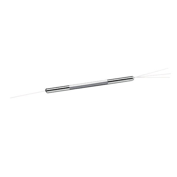
1×3 Single Mode Monolithic Fiber Optic Coupler/Splitter
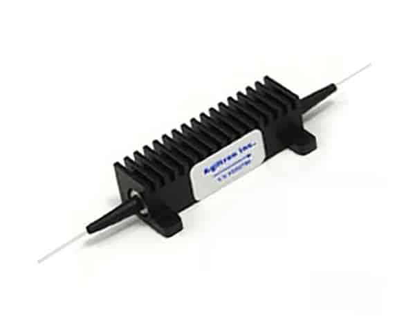
1x2/2x2 High Power Polarization Maintaining (PM) Fiber Optic Couplers/Splitters 30W
High Power 1x2, 2x2 Single Mode Fiber Optic Coupler/Splitter
High Power 1x2, 2x2 Multimode Fiber Optic Coupler/Splitter