Line width & sampling
Match the line profile, camera pixels and smallest surface feature.
Inspect, measure and process · Industry, inspection & flow
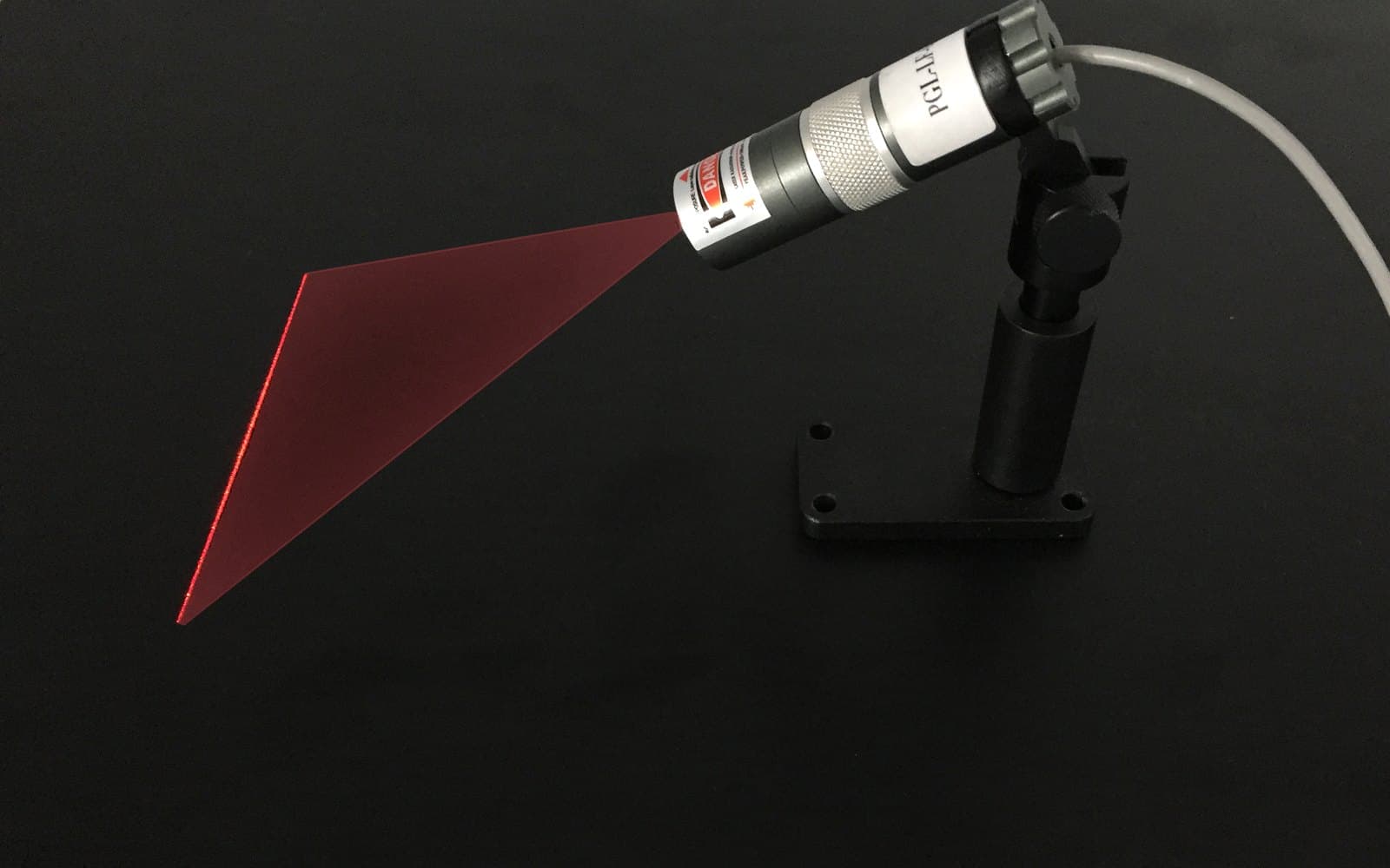
Turn a projected line into a calibrated surface profile.
Match the line profile, camera pixels and smallest surface feature.
Choose fan angle and working distance for the full measurement volume.
Balance wavelength, exposure and reflected light without saturation.
Why the source matters
The correct source is defined at the sample or process—not at the laser aperture. Wavelength and operating mode set the interaction; stability, delivery, timing, and control determine whether it stays useful in the complete system.
Application workflow
Three decisions turn the application into a practical source specification.
Set field width, standoff, height range, required resolution and scan speed. Calibrate the camera and laser geometry over that volume.
Specify fan angle, usable line length, width and uniformity at the working distance. Test the real surface, including dark and reflective areas.
Match line power and modulation to camera exposure and motion. Validate profile accuracy, repeatability and background rejection on representative parts.
Selection guide
These are starting architectures. Precisometer qualifies the final wavelength, output, delivery, control, and integration package against your setup.
OEM-MF suits a compact instrument when the mounting, driver and thermal path are designed together.
MDL-III offers up to 100 kHz modulation with PSU-A-D; other listed drivers are limited to 30 kHz.
MDL-XR-Line combines the driver and active temperature control in a 24 V DC head, with optional RS232.
Source architecture
375–1550 nm options · up to 15 W
Compact OEM head; separate driver
375–1550 nm options · up to 2.5 W
Separate head and power supply
450–1550 nm options · up to 15 W
Independent cooling; separate driver
405–808 nm options · up to 15 W
Independent cooling; separate driver
750–1060 nm options · up to 5 W
Independent cooling; separate driver
808 nm options · up to 20 W
Independent cooling; separate driver
375–1550 nm options · up to 5 W
Integrated driver and active cooling; optional RS232
Ready to specify
Specify field width, working distance, depth range, smallest feature, scan speed, surface finish, camera response and required line width.