Laser and optoelectronic control
Signal / Pulse Generator: Low-noise drive and current limiting protect the load while determining power stability and modulation fidelity.

Laser components & accessories
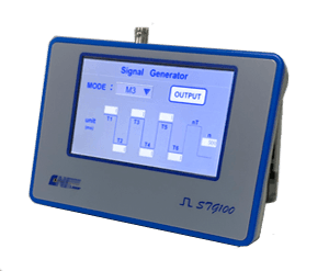
The SG-01 signal generator provides a configurable 0–5 V modulation signal for laboratory laser and optoelectronic control. Duty cycle, frequency and the receiving device’s trigger thresholds must be checked together before connecting the generator to a laser driver, shutter or modulator.
| Parameter | Listed value |
|---|---|
| Duty cycle | 1–99% |
| Modulation frequency | 0.1 Hz–100 kHz |
| Output voltage | 0–5 V |
| Integration check | Confirm input impedance, trigger threshold, polarity and common-ground requirements of the receiving device |
Application context
Application fit depends on the ordered configuration; catalog values are separated from fields that still require confirmation.
Signal / Pulse Generator: Low-noise drive and current limiting protect the load while determining power stability and modulation fidelity.
Signal / Pulse Generator: Known trigger levels, latency and duty-cycle limits allow the controller to synchronize with cameras, shutters and acquisition electronics.
Engineering reference
Signal / Pulse Generator is a configurable electronic driver or controller in the Laser components and accessories family. The final part number should be released only after the optical, mechanical, electrical and environmental fields below are matched to the intended instrument.
A driver or controller is selected against the electrical load and required optical behavior, not by connector appearance. Output range, noise, modulation bandwidth, protection functions and thermal interfaces must match the connected diode, modulator, stage or switch.
Selection guidance describes the engineering fields that must be checked. It does not assign an option-dependent value that is absent from the catalog record.
Technical FAQ
Confirm controlled load, output range, noise and stability, modulation and trigger, protection, and interface and cooling. These fields are coupled, so the final part number should be checked against the complete instrument rather than selected from the model name alone.
A driver or controller is selected against the electrical load and required optical behavior, not by connector appearance. Output range, noise, modulation bandwidth, protection functions and thermal interfaces must match the connected diode, modulator, stage or switch. Freeze the optical, mechanical and electrical interfaces before releasing the surrounding assembly.
Approve the configuration-specific specification, mechanical drawing, connector or pinout definition, environmental suffix and acceptance-test limits supplied with the quotation. Any field absent from the local record remains a confirmation item, not an assumed capability.