Back to Home

Precisometer lasers for optical metrology

UV lasers for metrology: replace your argon-ion source

Build your next interferometer, surface measurement or holographic setup around Precisometer’s CW UV sources.

Our UV-FN-349-SLM and UV-FN-360-X combine single-frequency output with stated linewidths below 1 MHz. Choose the source around your optical path, phase readout and required power, then qualify the upgrade from the legacy 351.1 or 363.8 nm argon line.

349 & 360 nm single-frequency choicesCW UV outputModel-specific datasheets

01 / UV source replacement

Choose your Precisometer UV metrology laser

Build the source specification around your measurement. Our 349 and 360 nm single-frequency CW lasers are the starting choices for coherent UV setups; our 364 nm CW source serves measurements led by intensity and spatial beam quality. We can help match wavelength, power, delivery and control to the instrument.

Single-frequency UV metrology

UV-FN-349-SLM

349 nm

50–100 mW CW

<1 MHz stated linewidth

Our starting recommendation for coherent UV measurements moving from a 351.1 nm argon line. Single-longitudinal-mode output and TEM00 beam quality support interferometric and holographic system design.

Specify this laser

Single-frequency UV metrology

UV-FN-360-X

360 nm

1–50 mW CW

<1 MHz stated linewidth

Choose our 360 nm source for phase-sensitive UV measurements designed around this wavelength. A practical route when an instrument using the 363.8 nm argon line can accept a qualified wavelength change.

Specify this laser

UV intensity measurements

UV-FN-364

364 ±1 nm

1–100 mW CW

TEM00 spatial mode · M² <1.5

Our nearby CW option for UV measurements where delivered intensity and beam quality lead the specification. For interferometry, request a source with an explicit single-frequency specification; this sheet does not establish SLM operation.

Specify this laser

Published source specifications: [2][3][6]. Confirm the ordered configuration, delivered power and the stability and calibration needed for your uncertainty budget.

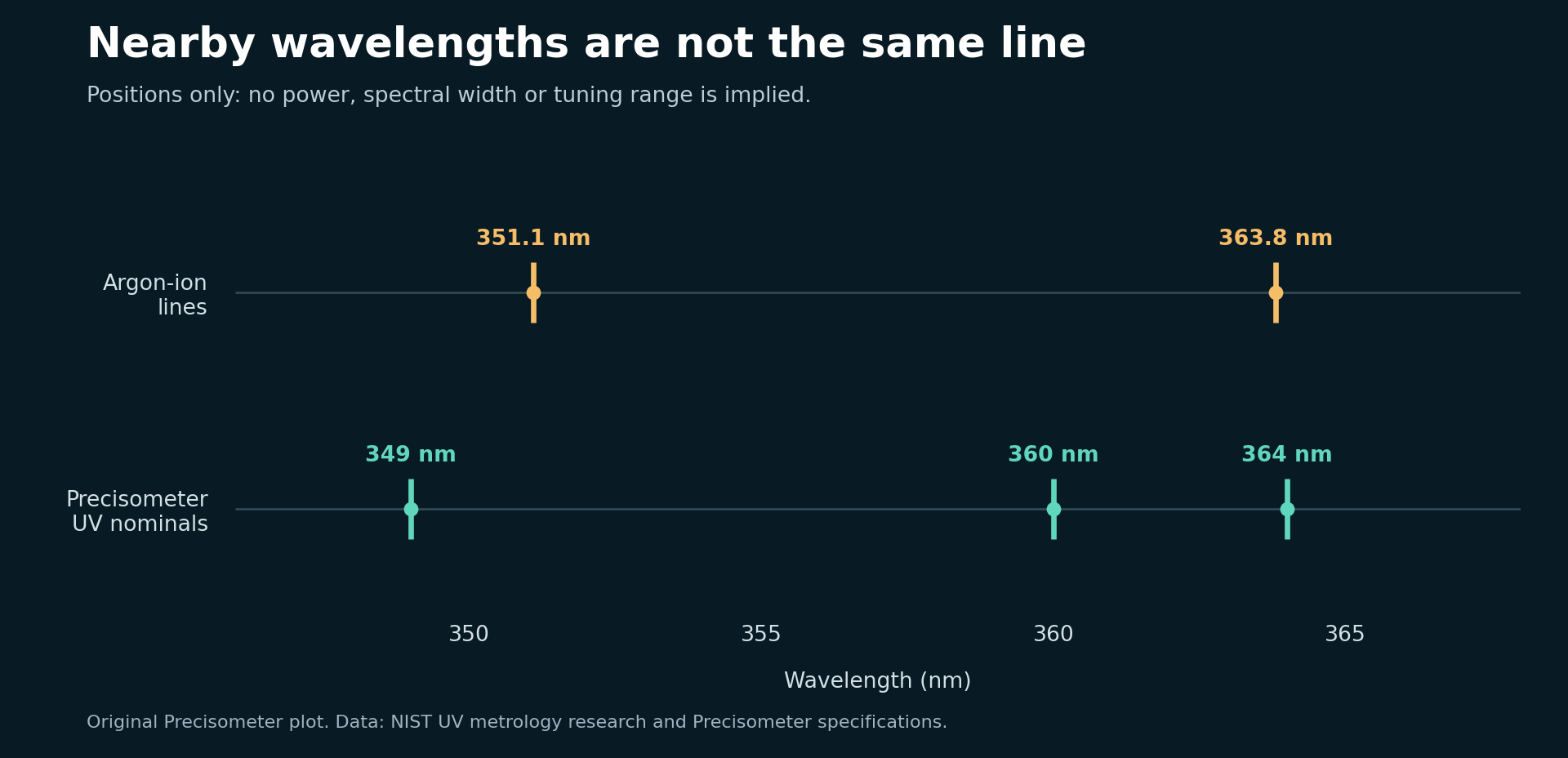
Wavelength comparison of 351.1 and 363.8 nm argon-ion lines with Precisometer UV source wavelengths at 349, 360 and 364 nm.
Original plot comparing argon-ion UV wavelengths reported in NIST metrology research with Precisometer source specifications. The colours distinguish source groups; they do not depict the appearance of UV light. No relative power, spectral linewidth or continuous tunability is implied. [1][2][3][6]

02 / UV source replacement

Put coherent UV light to work in your measurement

Displacement and vibration interferometry

Use the phase difference between a measurement beam and a reference to track motion. Start with our single-frequency 349 or 360 nm source, then define path imbalance, detector bandwidth, polarization and frequency stability for the readout. [2][6][8][9]

Surface and wavefront metrology

Build a phase-sensitive surface or wavefront measurement with the UV wavelength suited to your sample and optics. Our TEM00 single-frequency choices support a defined spatial mode and coherent reference path. Qualify phase noise, beam pointing and unwanted reflections in the assembled instrument.

Holographic and diffraction measurements

Supply coherent illumination for a UV holographic or diffraction-based measurement. Choose the line around the grating, detector and required optical path difference. Specify coherence, power at the instrument input and the polarization state together.

Normal-incidence reflection · constant refractive index

Δφ = 4πnΔx / λ0

Δx = λ0Δφ / (4πn)

λ0 is the vacuum wavelength and n the refractive index along the path. The factor of two in optical path comes from reflection. Transmission and oblique geometries need their own model. [7][8]

A useful phase scale for your design

In vacuum, a 1 nm reflector displacement produces about 36.0 mrad of phase change at 349 nm, or 34.9 mrad at 360 nm. These are calculated phase responses, not instrument resolution or accuracy specifications.

To turn phase sensitivity into a repeatable measurement, budget readout noise, wavelength uncertainty, drift, alignment and refractive-index changes. Our source datasheets provide the starting parameters; the complete measurement determines the uncertainty. [7][9]

03 / UV source replacement

Choose the UV upgrade around the measurement

UV argon configurations include lines near 351.1 and 363.8 nm. Record the line and delivered power actually used by the instrument. If it accepts a wavelength change, our 349 and 360 nm single-frequency sources offer routes to a modern CW UV design. Preserve an exact-line requirement when the sample, optics or measurement method demands it. [1][2][6]

Legacy lineCandidate nominalDifferenceQualification question
351.1 nm349 nm−2.1 nmStart with our UV-FN-349-SLM for a single-frequency CW upgrade; measure the new wavelength and update the interferometer scale.
363.8 nm360 nm−3.8 nmConsider our UV-FN-360-X when the measurement accepts 360 nm; requalify coatings, beam delivery and the wavelength scale.
363.8 nm364 nm+0.2 nmOur UV-FN-364 is a nearby CW option for intensity-based measurement. Specify SLM separately if coherence is required.

Choose the source around phase stability, calibrated wavelength, coating transmission, sample response and detector performance. A functional replacement is accepted by demonstrating the required measurement performance at the new wavelength.

When the exact 363.8 nm line is essential

Write the wavelength tolerance into the requirement and request a source characterized at that line. A 2025 research paper demonstrates single-frequency CW generation at 363.8 nm by tripling a 1091 nm fiber source, with more than 20 mW reported. This establishes a technical route; it does not establish a stocked product, lead time or guaranteed performance for a retrofit. [5]

04 / UV source replacement

Specify coherence and wavelength accuracy separately

SpecificationWhat it means for the replacement
Nominal wavelengthThe source’s named operating wavelength, such as 349 or 364 nm.
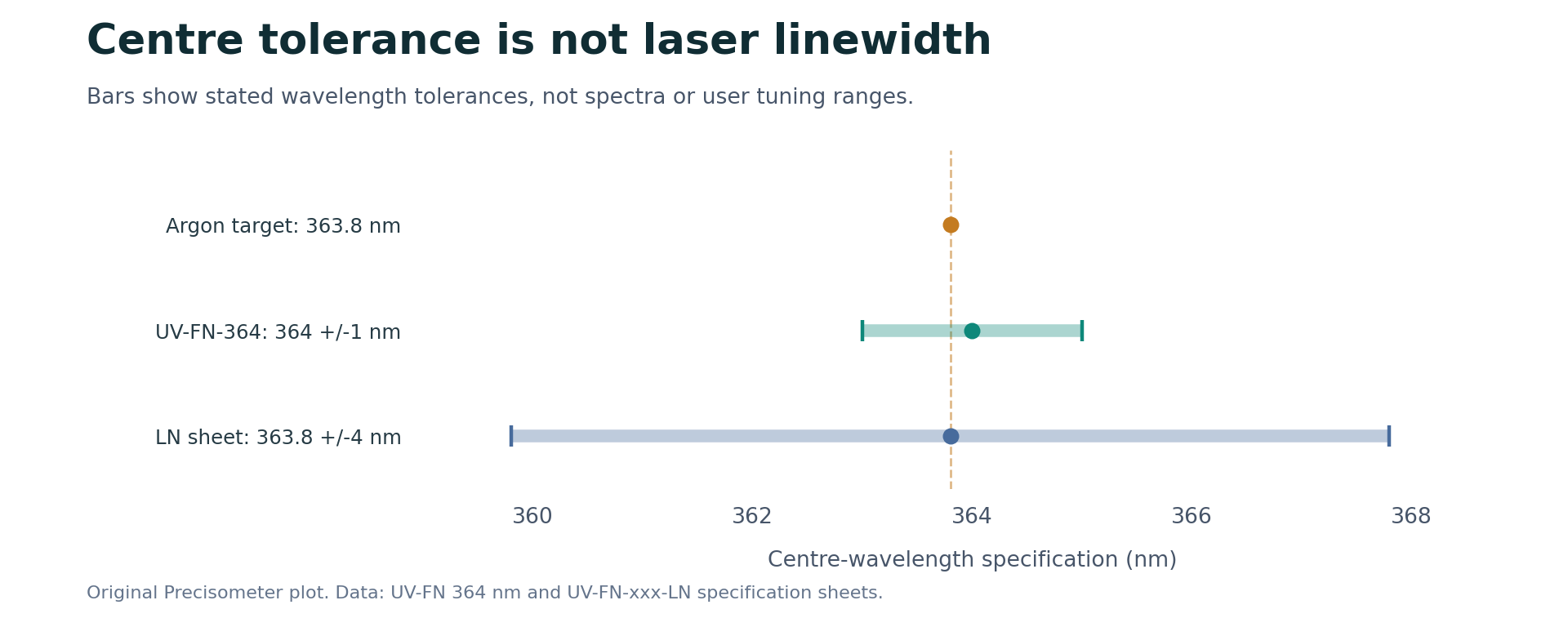
Centre-wavelength toleranceThe permitted range of the actual centre wavelength. It is not the linewidth and does not imply the user can tune across that range.
Single longitudinal mode / single frequencyA distinct spectral requirement for coherent or high-resolution measurements. Specify linewidth, side modes, drift and measurement conditions.
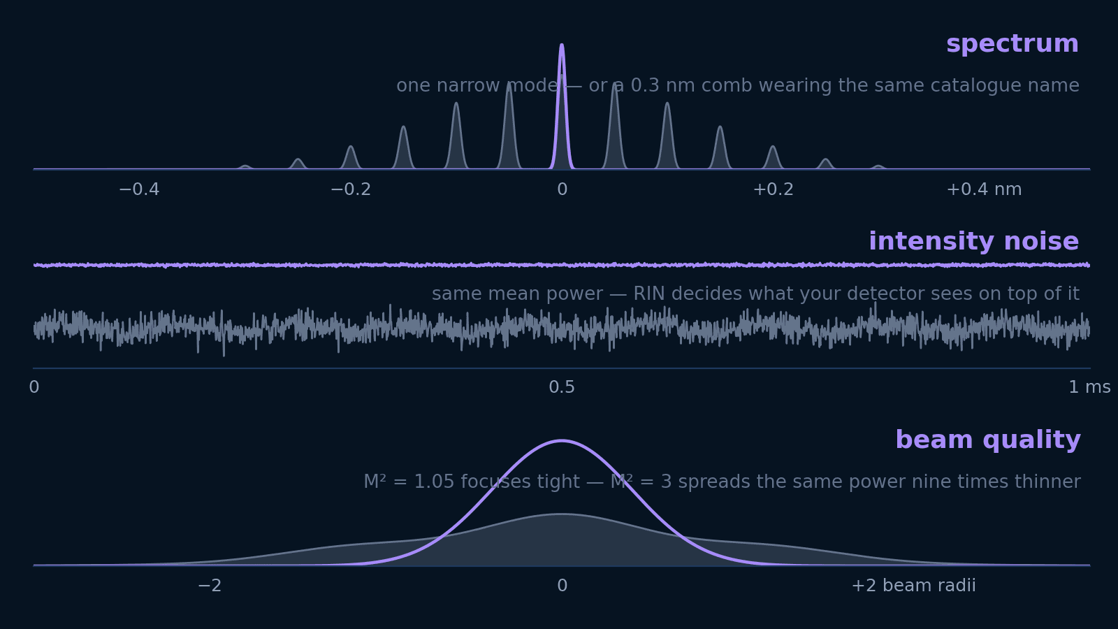
TEM00 / single transverse modeSpatial beam structure. It does not establish single-frequency operation.
Intensity noise and power stabilityTemporal fluctuations and drift, with their stated bandwidth, averaging and environmental conditions. A low-noise label alone gives no linewidth.

For a length measurement, the wavelength sets the scale. A narrow line supports coherence, while calibrated operating wavelength and frequency stability control different parts of the error budget. A nominal wavelength tolerance is not a statement of interferometric accuracy. In air, include refractive-index compensation appropriate to the UV wavelength. [7][8][9]

Our UV-FN-349-SLM specification, for example, separately lists 349 ±1 nm centre wavelength and <1 MHz linewidth. Use the centre-wavelength tolerance to set the permitted operating wavelength, and the linewidth to define the spectral requirement. Confirm the ordered configuration. [2]

Original plot comparing a 363.8 nm target with the stated 364 plus or minus 1 nm and 363.8 plus or minus 4 nm centre-wavelength specifications.
Original plot of stated centre-wavelength tolerances. The target marker does not show an argon linewidth. Neither bar is an emission spectrum, a tuning range or a promise of exact-line matching. [3][4]

05 / UV source replacement

Integrate the laser into your metrology system

Preserve CW operation when the method needs it

A UV wavelength does not specify CW or pulsed operation. At the same average power, a Q-switched source may have very different peak irradiance, timing and sample interaction. Request the temporal format explicitly, along with modulation bandwidth and extinction. Our UV-FN-349-SLM and UV-FN-360-X both specify CW operation. [2][6]

Check every wavelength-dependent component

Verify filters, dichroics, objectives, beam expanders, AOMs or AOTFs, detector response and UV fiber delivery at the new wavelength. Recheck throughput, alignment, polarization and sample-plane power. Existing component labels are not a measurement of the assembled path.

Update the interferometer scale

Use the measured new wavelength in the displacement conversion. In an ideal reflection measurement, keeping 351.1 nm in software while the source operates at 349 nm would overestimate displacement by about 0.602%—roughly 6.02 µm over a true 1 mm move.

Calculated as 351.1/349 − 1, holding refractive index and geometry fixed. This is a scale-setting example, not a performance claim for either laser. [7][8]

Measure utilities and integration needs

Compare electrical load, cooling, heat removal, footprint, warm-up, controls and service requirements for the actual configurations. Ask us to define the power supply and thermal interface for the selected Precisometer source. Base operating-cost comparisons on measured consumption and expected duty.

06 / UV source replacement

Agree the acceptance checks before the swap

  1. 01

    Baseline the old instrument

    Record the exact line or line set, power at the instrument and sample, beam profile, noise, calibration and a representative measurement.

  2. 02

    Set the wavelength requirement

    State centre wavelength and tolerance, the permitted method change, drift and whether wavelength tuning or locking is required.

  3. 03

    Set temporal and spectral limits

    Define CW or pulse format, linewidth, side-mode rejection, intensity-noise bandwidth and stability over a complete run.

  4. 04

    Verify optical and control interfaces

    Check beam height, waist location, polarization, coupling losses, modulation, shutter, monitoring, interlock and emergency-stop interfaces.

  5. 05

    Repeat the measurement on references

    Recalibrate with the new source, use matched sample conditions and compare signal, background, repeatability and relevant sample changes.

  6. 06

    Document the accepted configuration

    Retain the actual measured wavelength, delivered power, software settings, revised optical parts and the agreed pass criteria. Qualify the complete instrument.

Specify a Precisometer UV laser for your instrument

Tell us the measurement, argon line being replaced, path difference, required power and uncertainty target. We’ll help select the source configuration and identify the wavelength, stability, delivery and control requirements for your setup.

07 / UV source replacement

Common replacement questions

Which Precisometer UV laser should I start with for interferometry?

Start with UV-FN-349-SLM for a 349 nm design requiring 50–100 mW CW and a stated linewidth below 1 MHz, or UV-FN-360-X for 360 nm and 1–50 mW CW with the same stated linewidth class. Choose the wavelength around the instrument optics, sample and delivered power. Specify frequency drift, path difference and wavelength calibration separately.

Can our 349 nm source replace a 351.1 nm argon-ion line in a metrology system?

It can be considered when the system accepts the wavelength change and the required spectral, power and beam parameters are met. Use the new measured wavelength in the interferometer scale and validate against a reference. For an exact-line requirement, agree the actual centre wavelength and tolerance before ordering.

Is every 355 nm laser suitable for replacing CW argon-ion excitation?

No. Specify true CW output when the existing measurement requires it. A Q-switched 355 nm laser can have very different peak power, noise and timing at the same average power. Confirm the spectral and spatial requirements separately.

Does a narrow linewidth make the laser a calibrated length reference?

Narrow linewidth supports coherence, but interferometric scale accuracy also depends on the measured operating wavelength, frequency stability and refractive index along the beam path. Specify the calibration and traceability required by the complete instrument. The quoted source specifications alone do not establish a certified displacement accuracy.

When should I choose UV-FN-364?

Consider UV-FN-364 for an intensity-based UV measurement needing 1–100 mW CW near 364 nm and TEM00 spatial output. Its sheet does not specify single-frequency operation. For a phase-sensitive interferometer, start with an explicitly single-frequency source and qualify its wavelength and stability.

08 / UV source replacement

References and figure provenance

Both wavelength figures are original plots of cited numerical facts, drawn with standard plotting software. No third-party photograph, manufacturer drawing or research figure is reproduced. The linked documents retain their respective copyright and licence terms. Download the figure provenance record ↗

  1. [1]McClelland, J. et al., Journal of Research of NIST 108, 99–113 (2003). Accuracy of Nanoscale Pitch Standards Fabricated by Laser-Focused Atomic Deposition. Primary UV metrology research: Section 3 reports argon-ion output spanning 333.6–363.8 nm and diffraction measurements using the 351.1 nm line.
  2. [2]Precisometer specification library. UV-FN-xxx-SLM series specification. 349 ±1 nm, 50–100 mW CW and <1 MHz linewidth. The row heading says nm but its value explicitly uses MHz; confirm the agreed specification.
  3. [3]Precisometer specification library. UV-FN series: 364 nm specification. 364 ±1 nm, CW, 1–100 mW and TEM00. No linewidth or SLM specification is given in this sheet.
  4. [4]Precisometer specification library. UV-FN-xxx-LN series: 364 nm specification. The wavelength row states 363.8 ±4 nm. The low-noise label does not establish exact-line matching or single-frequency operation.
  5. [5]Wei, Z. et al., Optics & Laser Technology 185, 112611 (2025). Single-frequency continuous-wave solid-state 363.8-nm ultraviolet source generation by frequency tripling of a 1091-nm fiber laser. Research demonstration of a >20 mW single-frequency CW source at 363.8 nm; not a claim of a catalogue product or a guaranteed retrofit.
  6. [6]Precisometer specification library. UV-FN-xxx-X series specification. 360 ±1 nm, 1–50 mW CW and <1 MHz linewidth for the 360 nm column.
  7. [7]NIST. Wavelength References for Interferometry. Wavelength uncertainty, positioning accuracy and the effect of air refractivity. General metrology principles; no UV source certification is implied.
  8. [8]Stone, J., Phillips, S. D. and Mandolfo, G. A., Journal of Research of NIST 101, 671–674 (1996). Corrections for Wavelength Variations in Precision Interferometric Displacement Measurements. Primary derivation of the reflection-interferometer phase relationship and wavelength corrections. The guide writes the wavelength in terms of vacuum wavelength and refractive index.
  9. [9]Pedulla, J., Deslattes, R. and Lawall, J., NIST (2000). A Frequency Stabilized Laser Array for Use in Displacement Metrology. Primary metrology research illustrating why short-term spectral behaviour and long-term frequency stability are separate requirements.