A crystal has an internal reference frame
In an ordinary periodic crystal, atoms form an ordered structure built by repeating a unit cell. A single crystal maintains one lattice orientation across the region of interest; a polycrystalline solid contains grains with different orientations. An amorphous region lacks the long-range order needed for an indexable single-crystal Laue pattern.[1]
The cell edges a, b and c define the crystal axes. Miller indices (hkl) label parallel lattice planes through reciprocal intercepts: a zero means the planes are parallel to that axis. [uvw] denotes a direction; braces {hkl} denote symmetry-equivalent planes. In cubic crystals [hkl] is normal to (hkl); that shortcut does not hold for every crystal system.[2]
(100) planes
x = 1
Parallel to b and c
(110) planes
x + y = 1
Parallel to c
(111) planes
x + y + z = 1
Cuts all three axes
The specimen’s visible face need not coincide with a chosen lattice plane. Define the required plane or direction and its angle to the sample surface, holder or cutting axis. That is the orientation a Laue measurement helps establish.
Why a white X-ray beam makes spots
X-rays scattered by successive lattice planes reinforce one another when their path difference is an integer number of wavelengths. Bragg’s law expresses this condition:
nλ = 2d sin θ
d: plane spacing · λ: wavelength · n: diffraction order · θ: angle between the incident beam and the planes. The scattering angle between incident and diffracted beams is 2θ.[3]
Laue diffraction uses a broad, or “white”, spectrum. At one crystal setting, different plane sets can satisfy Bragg’s law at different wavelengths, producing many spots on an area detector. Indexing assigns reflections to a crystal model and solves its orientation.[4]
Laue is itself an X-ray diffraction method. A conventional powder scan usually records intensity against 2θ to investigate phases or lattice spacings.[9] A laboratory Laue orientation instrument instead uses the geometry of a spot pattern to align a crystal; it complements structure-analysis measurements.
Back-reflection
Transmission
Back-reflection collects diffracted rays on the source side and suits specimens that do not transmit the beam. Transmission puts the detector beyond the sample and requires sufficient X-ray transmission. There is no universal thickness cutoff: material, photon energy and geometry matter.[4]
Turn a pattern into a usable orientation
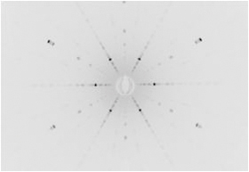
A pattern is a map of scattering directions, rather than a photograph of atoms. Use the measured and predicted spot positions together. Photonic Science’s software overlays simulated patterns, detects spots, calculates misorientation and exports angular results. A visually symmetric image alone does not establish the required alignment.[5]
- Define the task. Record the material, crystal model, target plane or direction, and angular tolerance.
- Mount and locate. Secure the specimen and set the calibrated measurement position. Make the sample-to-holder reference reproducible.
- Acquire and index. Adjust exposure to resolve spots without saturation, then check that the model explains several reflections across the image.
- Align and remeasure. Apply the required rotations and verify the final setting. Save the pattern, orientation, reference frame and sample identifier; include loading and verification in cycle-time estimates.
Split or broadened spots can warrant investigation, but beam divergence and detector blur also affect spot shape. One exposure samples the illuminated region: it cannot certify an entire specimen as defect-free. Check additional positions when local grains or orientation changes matter.[4]
Worked example · silicon
Align [001] with the beam
Suppose a silicon crystal must have its [001] direction parallel to the incident beam. Define the beam as laboratory z and record the holder reference. In cubic silicon, [001] is normal to (001); aligning this direction alone leaves rotation about it free. Specify a second direction if the in-plane orientation matters.
Mount and acquire
Secure the crystal, set the calibrated sample position and acquire a pattern with resolved, unsaturated spots. Choose the silicon crystal model.
Index the pattern
Match predicted and observed positions across several reflections. Read the fitted [001] direction in the laboratory frame; the brightest spot alone does not identify that axis.
Apply the correction
Convert the fitted orientation into the calibrated goniometer coordinates. The calculation below shows a simple case with tilt about one axis only.
Verify with another exposure
After moving, acquire and index again. Compare the fitted angle to the application tolerance, then save the pattern, orientation, coordinate convention and holder reference.

- 1 · Exclude the central region. Keep the detector opening out of spot detection. Use the calibrated beam centre and detector geometry.
- 2 · Locate a spot centre. Compare its position with a prediction. Its brightness alone does not establish an (hkl) label.
- 3 · Check separated reflections. The same fitted orientation should explain spots in different parts of the detector.[5]
A 5° correction, calculated
Assume the fitted unit vector for [001] is (sin 5°, 0, cos 5°), approximately (0.08716, 0.00000, 0.99619). Its tilt from z lies entirely in the x–z plane. A right-handed rotation of the crystal by −5° about laboratory y brings that vector onto z.
- Assumed initial tilt
- 5°
- Calculated y rotation
- -5°
- Ideal corrected direction
- (0, 0, 1)
Illustrative geometry, not measured performance or a motor command. Real instruments use different axis conventions; obtain the stage rotation from the calibrated coordinate mapping. Acceptance comes from the new diffraction measurement, not the ideal vector calculation.[10]
Match the system to the specimen and workflow
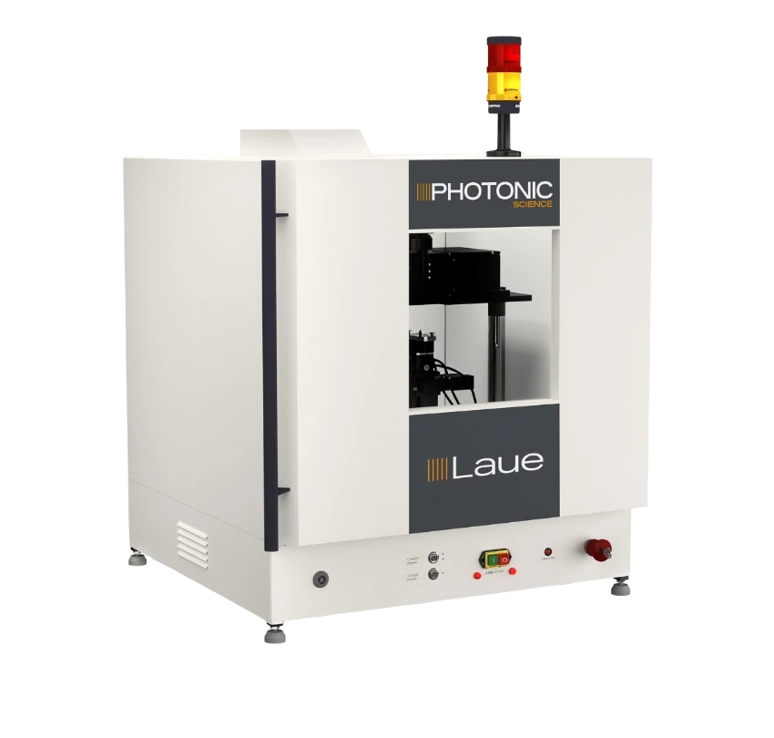
Compare the Photonic Science systems below, then check the complete holder and rotation envelope. “Typical exposure” covers image acquisition; it is not the total time per sample.[6]
| System / fit | Typical exposure | Accuracy, down to | Maximum sample envelope |
|---|---|---|---|
Occasional orientation of smaller samples; longer exposures are acceptable. | 120–240 s typical | 0.2° | 50 × 50 × 26.5 mm |
Routine alignment and repeated measurements within the chosen geometry. | 1–30 s typical | 0.1° | 250 × 250 × 40 mm horizontal; 250 × 150 × 40 mm vertical |
Larger specimens that need the extended sample envelope. | 1–30 s typical | 0.1° | 450 × 250 × 250 mm |
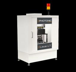
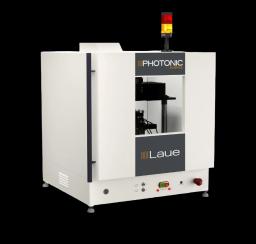
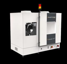
Manufacturer figures for the published configurations. Accuracy depends on calibration, positioning, sample and analysis; confirm performance for your material and tolerance. Sample dimensions are not stage travel or guaranteed clearance during rotation.
A horizontal configuration can suit transfer to a cutting workflow; a vertical layout supports trays and scanning. Grain mapping requires the appropriate positioning, optics and software, with a beam small enough to distinguish the regions of interest. Confirm motorisation and alignment-camera availability for the selected model.[7]
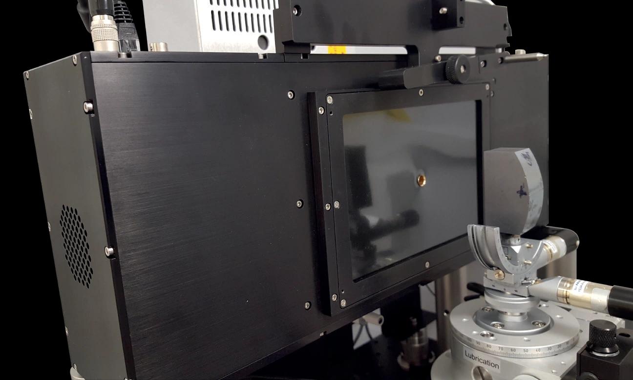
Integrating an existing instrument? The X-ray Laue back-scattered camera provides a central beam opening and a nominal 155 × 105 mm active input.[8] A detector purchase still needs a compatible source, shielding, mechanics and analysis. For a complete system, confirm the cabinet, source, detector, PC/software, stages, holder, distance tool and commissioning in the configuration. Use the instrument within its approved operating procedure.
Plan your Laue measurement with Precisometer
Send the material, sample and holder dimensions, target orientation, angular tolerance and batch size. We’ll help select the system, geometry and accessories, confirm what is included and prepare a quotation.
Ask for a Laue system recommendation →Sources and further reading
- IUCr: Crystal: long-range order and periodic structures.
- IUCr: Miller indices and lattice-plane notation.
- IUCr: Bragg’s law.
- J. R. Helliwell, International Tables for Crystallography: Single-crystal X-ray techniques.
- Photonic Science: Laue software and public pattern gallery.
- Photonic Science: Laue-LT, Laue and Laue-XT specifications.
- Photonic Science: System geometry and options.
- Photonic Science: X-ray Laue detector.
- International Centre for Diffraction Data: What is powder diffraction?
- IUCr: Orientation matrices and instrument coordinate conventions.