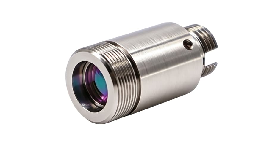
1. The Optical Advantage: Why Aspheric Singlets Beat Spherical & GRIN Lenses
Standard spherical lenses suffer from inherent spherical aberration: marginal rays entering near the edge of the lens refract more strongly than paraxial rays near the optical axis. This creates multiple focal points, severely distorting the wavefront, broadening the far-field divergence, and degrading beam quality factor (M² > 1.4).
Diffraction-Limited Wavefront (M² ≈ 1)
By carefully varying surface curvature from center to edge, an aspheric surface refracts all rays to a single stigmatic focal point. The resulting collimated beam preserves the single-mode fiber’s fundamental Gaussian profile (TEM₀₀) with virtually no wavefront distortion.
Zero Cement Boundaries & High Damage Threshold
Unlike achromatic doublets that use optical adhesive between crowns and flints, aspheric collimators use a monolithic optical glass element. There is no glue layer to solarize under UV exposure or burn under high-power pulsed fiber laser delivery.
Broadband AR Coating (T > 95%)
Both optical surfaces are coated with multilayer dielectric anti-reflective films tailored to specific laser bands (VIS, NIR, Telecom). Reflection losses are kept below 0.25% per surface, preventing destabilizing backreflections and internal cavity resonance.
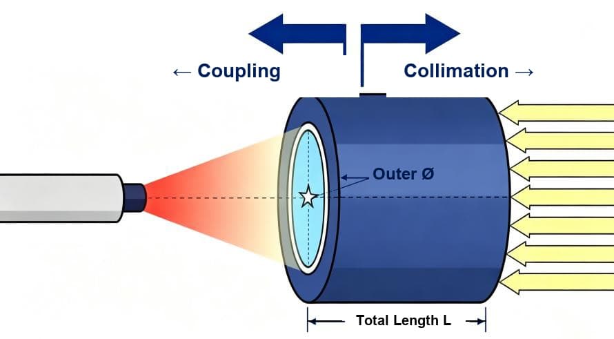
2. The Two Golden NA Matching Laws: Collimation vs. Coupling
Numerical Aperture (NA = n · sin θ) governs the angular cone of light that an optical element can accept or emit. A frequent design mistake is applying the same rule in both propagation directions:
Fiber → Space (Collimation)
The collimating lens must have an acceptance numerical aperture larger than the fiber output divergence cone to collect all emitted light without peripheral vignetting or diffraction rings.
Space → Fiber (Coupling)
The convergence cone of the focused free-space beam must fall safely inside the fiber’s critical acceptance angle so that all optical power is trapped within the guided core mode.
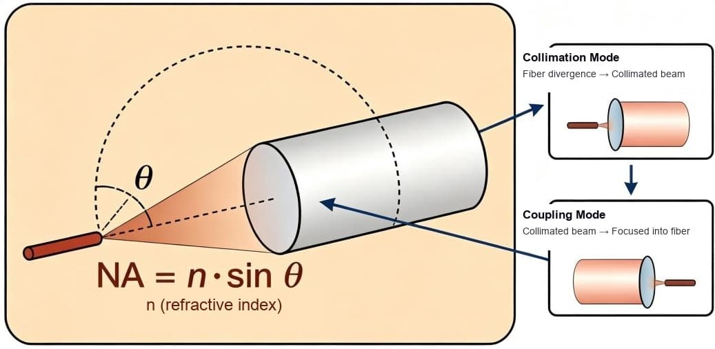
3. Interactive Beam Waist & Divergence Calculator
Use this interactive engineering tool to calculate output beam diameter (2w₀), full-angle divergence (θ), and depth of focus (Rayleigh range) for any fiber and lens combination:
Aspheric Fiber Collimator & Beam Sizing Lab
Calculate output beam diameter, far-field divergence, Rayleigh range, and automatically select the matching collimator product.
Pick a Zolix factory model to load calibrated focal length, NA, and standard fiber parameters.
Standard Fiber & Wavelength Presets:
8° polish suppresses backreflection (>60 dB return loss).
Collimated waist at lens output
1.11 mrad far-field spread
Collimated beam depth of focus
1.5× margin prevents edge diffraction
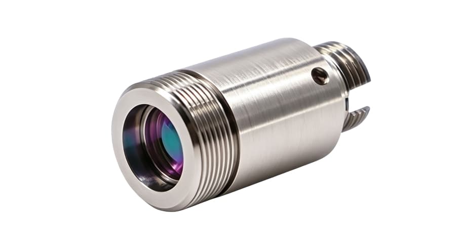
AFC-FC-APC-780780 nm FC/APC Aspheric Fiber Collimator
Single-mode aspheric collimator for 780 nm rubidium D2 transition spectroscopy, atomic clocks, and Ti:Sapphire laser delivery.
Numerical Aperture Verification: Passed
Optimal: Lens NA (0.45) is sufficiently larger than fiber NA (0.13) to capture 100% of the divergent light cone without peripheral clipping.
4. Calculating Output Beam Waist & Clear Aperture Sizing
For single-mode fiber emission, the beam is characterized by its Mode Field Diameter (MFD) rather than the physical core diameter. The output collimated beam waist diameter (2w₀) is derived from the Fourier transform of the fiber mode:
Beam Diameter & Divergence Equations
2w₀ ≈ (4 · λ · f) / (π · MFD)
θ_full ≈ MFD / f ≈ (4 · λ) / (π · 2w₀)
z_R = (π · w₀²) / λ
Where f is the lens focal length, λ is wavelength, MFD is mode field diameter, and z_R is the Rayleigh range over which the beam remains reasonably collimated.
The Downstream Clear Aperture Requirement
A Gaussian beam’s intensity decays exponentially, but never drops abruptly to zero. If you pass a collimated beam of diameter 2w₀ through an optic with clear aperture equal to 2w₀, approximately 13.5% of the total laser power is truncated at the edges!
Minimum requirement: Clear Aperture ≥ 1.5 × 2w₀ (> 99% transmission)
Precision interferometry: Clear Aperture ≥ 2.0 × 2w₀ (> 99.9% transmission)
Failing to respect this margin causes concentric diffraction rings (Airy disks) that ruin beam homogeneity in imaging and microscopy.
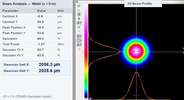
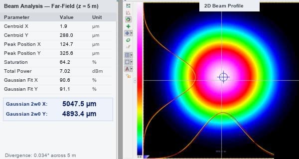
Empirical Beam Profiler Validation: 0 m Waist vs. 5 m Far-Field
Beam profiler measurements of a single-mode 633 nm laser beam delivered through a Zolix aspheric collimator. The near-perfect Gaussian circularity (TEM00, M² ≈ 1.0) is preserved over a 5-meter propagation distance with full-angle divergence of just 0.034°:
5. Fiber Connectors: FC/PC, FC/APC, and SMA905
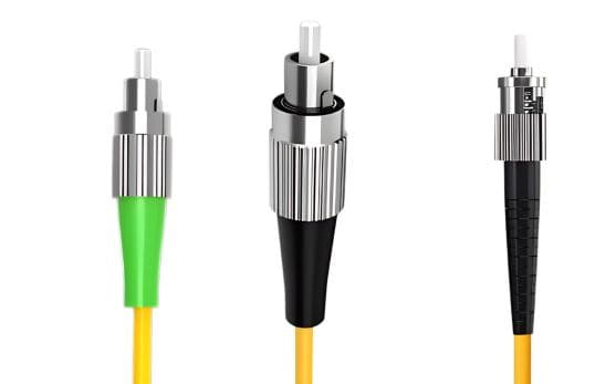
The collimator receptacle must match your fiber patch cable exactly. Fiber connectors differ in ferrule geometry, polish angle, and optical return loss:
| Connector | Endface Polish | Return Loss | Typical Applications | Critical Rule |
|---|---|---|---|---|
| FC/PC | Physical Contact (0° flat convex) | ≥ 45 dB | Standard laboratory test benches, visible laser delivery, routine spectroscopy. | Never mate with FC/APC. Flat face cannot seal against an 8° angled ferrule. |
| FC/APC | Angled Physical Contact (8° angle) | ≥ 60 dB | Single-frequency DFB/ECDL lasers, coherent communications, optical frequency combs, high-power fiber amplifiers. | Green strain-relief boot. Backreflected light is deflected into cladding rather than traveling back into the cavity. |
| SMA905 | Air-gap / Flat Contact | 20 ~ 30 dB | High-power industrial lasers, large-core multimode fibers (≥ 100 µm), spectroscopy probes, medical lasers. | Threaded coupling nut with high mechanical pull strength; not intended for single-mode interferometric applications. |
6. Four Costly Collimator Selection Pitfalls (And How to Avoid Them)
Avoid these common hardware mismatches before requisitioning components for your opto-mechanical setup:
1. Checking Only the Center Wavelength
Broadband sources (such as supercontinuum lasers, ASE sources, and femtosecond lasers) span tens or hundreds of nanometers. Standard anti-reflection (AR) coatings have sharp transmission roll-offs outside their rated band. Confirm that transmission exceeds 95% across the entire source bandwidth, not just at peak emission.
2. Under-sizing Downstream Mirrors and Filters
A Gaussian beam contains 86.5% of its power within the 1/e² diameter (2w₀). To transmit >99% without diffraction edge clipping, every downstream mirror, beam splitter, or filter clear aperture must be at least 1.5× larger than 2w₀ (ideally 2.0× for interferometric setups).
3. Cross-Mating PC (Blue) and APC (Green) Connectors
An 8° angled APC ferrule inserted into a flat PC receptacle leaves an air wedge between the glass cores. This causes catastrophic insertion loss (>10 dB), creates severe backreflection, and can physically chip the delicate core edges upon tightening.
4. Overlooking Fiber Minimum Bend Radius and Barrel Envelopes
In optical cages or custom instrument enclosures, verify that the outer diameter (e.g. Ø11 mm or Ø12 mm) fits existing mount clamps and that the fiber behind the connector has adequate clearance to maintain its minimum bend radius (>30 mm for standard telecom SMF).
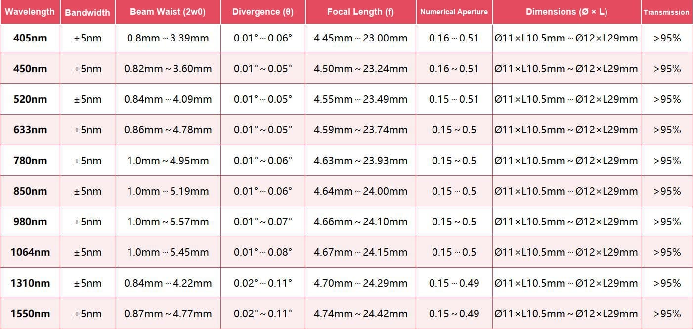
7. Standard Aspheric Collimator Matrix & Wavelength Coverage
Standard pre-aligned aspheric collimator models across visible, near-infrared, and telecommunication bands with corresponding waist sizes, divergence angles, and focal lengths:
Need Precision Aspheric Collimators for Your System?
Precisometer provides Zolix precision aspheric fiber collimators with custom focal lengths, pre-aligned FC/PC, FC/APC, and SMA905 receptacles, and broadband AR coatings from UV to Telecom wavelengths.
Before you specify
Guides that cover this decision
 Photonics
How to fiber-couple a diode laser
Take an asymmetric diode beam from collimation through mode matching, SM/MM/PM fiber selection, alignment, polarization, feedback control, and long-term stability.
Open guide Opto-mechanics
Optical cage systems: why to use one, and how to build with it
Four rods do not make a system more accurate — they make four degrees of freedom per optic disappear. The error budget that proves it, the over-constraint that is the price, and a build sequence with real 30 mm part numbers.
Open guide Integrated photonics
Fibre-to-Chip Alignment: Choosing Stages, Feedback, and Fixation
From coupling geometry and mode-field tolerance to manual, motorized, and piezo stage selection, optical feedback loops, first-light search workflows, adhesive fixation with UV cure monitoring, and three worked equipment configurations.
Open guide