Opto-mechanics
Why build in a cage
Four rods do not make an optical system more accurate. They make most of it non-adjustable — and that is a different, better thing to buy.
4 DOF removed per optic
A plate on four rods keeps only its position along the axis and its rotation about it. Everything else was decided by the geometry of the rail.
θ ≈ e / f
A decentred lens steers the beam. Half a millimetre of placement error on an f = 50 mm lens is 10 mrad of pointing — the term that dominates a posted build, and the one rods collapse.
8 constraints, 4 needed
The same four rods are a redundant constraint set. It is why a cage is quick and repeatable, and why it is the wrong frame for anything specified in nanometres.
Interactive lab
What the rods are worth, in micrometres
Posted mounts
Each optic on its own post, post holder and mount, referenced to the table.
- Beam offset at target
- 7.50 mm
- Pointing error
- 27.39 mrad
- DOF to set by hand
- 30
- Coupling, before touch-up
- < 0.01 %
5 DOF per optic — height, lateral, longitudinal, tip, tilt — every one of them free until you set it.
30 mm cage
Every optic on a plate threaded onto the same four rods.
- Beam offset at target
- 1.45 mm
- Pointing error
- 5.28 mrad
- DOF to set by hand
- 6
- Coupling, before touch-up
- < 0.01 %
1 DOF per optic — position along the rods; tip, tilt and both transverse axes are set by the geometry.
The cage build lands 5.2× closer to the target and leaves you 24 fewer degrees of freedom to chase. Neither build is finished at this point — both still need a fine adjustment at the target. The difference is whether that adjustment starts inside capture range.
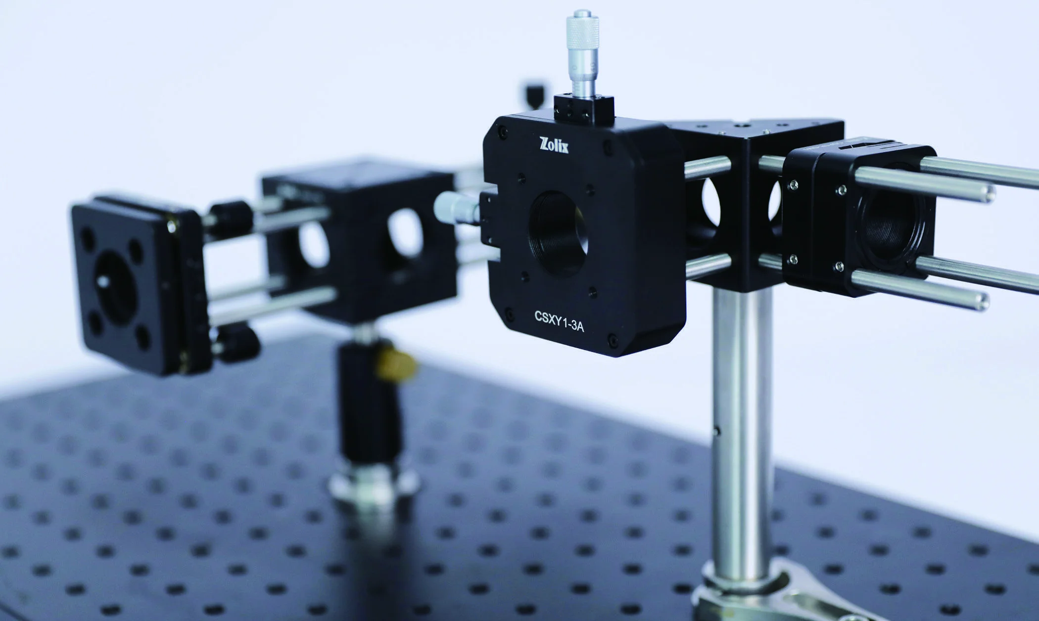
On these numbers ±3 mm of XY travel is the honest choice — CSXY1-3. Decentre accounts for 86 % of the caged build's angular error budget: shorten the focal length and it dominates, lengthen it and mount tilt takes over.
Start here
The argument for a cage is about degrees of freedom, not precision
A rigid optic on a good kinematic mount, aligned carefully by someone who knows what they are doing, will beat a cage plate on absolute accuracy. That is not the comparison that matters. The comparison that matters is what happens across a train of six or eight optics, where each one arrives with five degrees of freedom free — height, lateral position, longitudinal position, tip and tilt — and every one of them has to be resolved against a beam you can only see where it lands.
Slide those same optics onto four rods and four of those five are gone. Not aligned: absent. The plate cannot sit off-axis because the bores are where the rods are, and it cannot tilt because two rods separated by 30 mm will not allow it. What remains is the spacing along the axis, which is a dimension you can order rather than an adjustment you have to make.
The consequence is not that the first alignment is better. It is that the first alignment is shorter, and that the second one — after the rebuild, after the move, after the year — is nearly free. Run the error budget above with six optics and an f = 50 mm train and look at the beam offset the two builds deliver at a single-mode fibre. Both need a fine adjustment at the end. Only one of them starts inside the capture range of the mount you would buy to make it.
Four constraints you never have to set
A plate threaded onto four rods has its two transverse positions and its two tilts decided the moment it slides on. What is left is position along the axis and rotation about it. You are not aligning the optic to the beam any more — you are aligning one axis, once, and then hanging optics on it.
Spacings that are dimensions, not adjustments
A 100 mm separation between two lenses becomes a 100 mm tube, cut to length by the manufacturer and repeatable to the thread. On posts it is a measurement someone makes with a ruler, and it changes every time the assembly is disturbed.
Rebuilds that land where they landed before
This is the property people underestimate. Take a caged relay apart and put it back and you return to within the clearance fits. Take a posted one apart and you have thrown away every hour of alignment that went into it.
A tube is a baffle you did not have to design
Enclosing the path kills the room light, the stray reflection off the far wall of the lab, and the fluorescence of somebody’s open laptop. In a weak-signal experiment that single side effect is often worth more than the alignment argument.
The part the brochures omit
Four rods through four bores is an over-constrained assembly
Count it properly. Each rod passing through a bore removes two translations at that point, so four rods impose eight constraints. The degrees of freedom they are there to remove — two transverse translations and two tilts — number four. The other four constraints are redundant, and a redundantly constrained assembly only goes together because of clearance.
That clearance is the whole design. It is why the plate slides, why the residual decentre is what it is, and why the rail tolerates rods that are not perfectly parallel. It is also why the assembly stores energy: tighten all four clamp screws on a plate and the rail's geometric error stops being free motion and becomes internal force. On a plate holding a 3 mm-thick window nobody notices. On a plate holding a thin mirror substrate it appears as astigmatism in the reflected wavefront, and people spend a long time blaming the coating.
The thermal version of the same argument is worth a number. A 300 mm 6061 rail grows about 7 µm per kelvin along its own axis — irrelevant to pointing, occasionally relevant to focus. But a gradient across the rail is a bimetallic strip: to first order, one kelvin between the top and bottom rod pair over a 30 mm spacing bends a 300 mm rail through roughly 0.2 mrad, with about 35 µm of deflection at the end. A laser head at one side of the rail, or an air conditioner blowing across it, is enough. Symmetry is what protects you here, not stiffness — which is an argument for keeping heat sources off the rail rather than for making the rods thicker.
The 30 mm standard
Six numbers that decide every build
| Rod spacing | 30 mm square | Four Ø6 mm rods on the corners of a 30 mm square, centred on the optical axis. The 60 mm standard exists for larger optics and mixes through adapters. |
|---|---|---|
| Rod diameter | Ø6 mm | Stiffness scales as the fourth power of diameter, so a 60 mm cage on Ø6 mm rods is not simply a bigger 30 mm cage — the span grows and the section does not. |
| Optic thread | SM1 · 1.035"-40 | Accepts a Ø25.4 mm optic against a retaining ring. Clear aperture through the assembled tube is roughly Ø23 mm, not Ø25.4 mm. |
| Plate thickness | 9 mm | CSP1 series. It is the number that turns a list of optics into a rod length, and it is the one people forget when they add up spacings. |
| Post mounting | M4 | The rail still has to reach the table. A cage that is well aligned internally and badly mounted externally has moved the problem, not solved it. |
| Material | 6061-T6, black anodised | α ≈ 23.6 ppm/K. A 300 mm rail moves about 7 µm per kelvin along its own axis. |
How to build one
Eight steps, in the order that saves the most time
The sequence matters more than the parts. Nearly every slow cage build is slow because the axis was never properly established before optics went onto it, and the rest of the assembly then spent its life expressing that error rigidly.
Define the axis before you own a single optic
Two irises at the same height, far apart, set by the beam you already have. This is the only alignment in the whole build that is done the old way, and everything downstream inherits it. Get it wrong and the cage will hold your optics rigidly in the wrong place.
Mount the rail to the table, then check the axis again
Coaxial post adapters carry the rail on standard posts; a base plate bolts it down where you want it fixed. Clamping to the table almost always moves the axis by a fraction of a milliradian, which is why you check afterwards rather than trusting the check you did before.
Build outward from whatever cannot move
A fibre launch, a detector, a sample stage, a monochromator slit — something in the system is fixed by the rest of the experiment. Start there and let the tolerance accumulate towards the end you can still adjust, not towards the end that is bolted down.
Use one rod set per span, and add length for later
Every joint in a rod run is a new concentricity error and a new place for the rail to sag. Order rods long enough that the next component fits without rebuilding the run — the cost difference between a 200 mm rod and a 250 mm one is far less than an afternoon.
Snug the clamp screws — do not torque all four
Four rods through four bores is a redundantly constrained assembly. It works because of clearance. Drive all four setscrews hard on a plate holding a thin optic and you are loading that optic through the plate; on a mirror substrate it shows up immediately as astigmatism in the wavefront.
Put every adjustment where the sensitivity is
Do not distribute adjustment along the rail because it is available. One tip/tilt near the input, one XY or XYZ at the coupling, and rigid plates everywhere else converges quickly. Adjusters at every station give you a system that has more solutions than you have patience.
Fill the spacings with tubes, not with air
Tubes set the spacing, hold the optics against retaining rings, and block everything that is not your beam. Fill a gap with the longest tube that fits and take the remainder up on the ring position, rather than stacking four short sections and four extra joints.
Fold with a cube or a bracket, and re-establish the axis
A cage cube keeps the fold inside the standard so the second arm arrives on rods rather than on faith. Right-angle plates and 30-to-60 adapters do the same job for arms that change scale. Whichever you use, the new arm has its own axis and deserves its own two-iris check.
Worked example
A fibre launch, priced in millimetres
Take the arithmetic the rail planner above does, and do it once by hand so the numbers are not a black box. A collimated free-space beam has to be filtered and launched into a single-mode fibre. Four stations: collimating lens, clean-up filter, launch lens, fibre coupler.
Carriers first. Two CSP1-SM1 plates at 9 mm each is 18 mm. A sliding filter mount and an XYZ coupler are not 9 mm plates — call them 12 mm and 25 mm from their drawings, and flag both as numbers to confirm rather than to trust. Carriers total 55 mm. Clear gaps of 40, 60 and 25 mm add 125 mm. The rail is 180 mm.
Rods next. Add 15 mm of overhang at each end so the next component does not force a rebuild, and you need 210 mm. The catalogue's next size up is 250 mm, so CSSP-250-P4 — and the 70 mm of spare rod is not waste, it is the room to add an iris or a beam sampler later without dismantling the run.
Then the tubes. The 60 mm gap takes a CSSM1-50A plus a CSSM1-8A, leaving 2 mm to take up on the retaining rings. The 40 mm gap takes a 38 mm tube and 2 mm of ring. The 25 mm gap takes one CSSM1-25A exactly. Three spans enclosed, three fewer paths for room light into a measurement that will eventually be photon-starved.
Finally, adjustment. One tip/tilt at the input on a CSRA1-A, one CSXYZ1-1.5 at the fibre, and rigid plates in between. Run the error budget for this train — four optics, roughly 60 mm apart, f = 50 mm, launching into a 4.3 µm mode field — and the caged residual sits comfortably inside ±1.5 mm of travel. The posted equivalent does not, which is the whole argument in one number.
What to buy
Five families, and what each one is for
Structure
The rail itself: rods in matched sets of four, short studded rods for two-plate sandwiches, adapters where a run has to be extended, and the parts that bring the axis down to the table.
Optic carriers
Plates for the standard bores, SM1 tubes for spacing and stray-light control, and dedicated carriers for the optics that do not sit flat in a bore.
Adjustment
The few places where you deliberately keep a degree of freedom. Buy the travel you calculated, not the travel that was in stock — a ±1 mm mount asked to take up 2 mm of build error is simply a fixed mount.
Folding and scale change
Cubes keep a 90° fold inside the standard; brackets and adapter plates take an arm to a new axis or from 30 mm to 60 mm without leaving the rails behind.
When not to
Five setups where a cage is the wrong answer
A cage is a constraint system, and constraint is only useful where you already know what the geometry should be. Where you do not, or where the geometry is not rectilinear, it turns into an expensive way of holding optics in approximately the wrong place.
Your fold is not 90°
Cages are a rectilinear standard. A 22° fold, a Littrow grating, a prism at minimum deviation or a pump-probe geometry with a deliberate crossing angle all leave the standard immediately. Build those on a table with kinematic mounts and use the cage only for the collimated runs between them.
The optic is larger than the aperture
A Ø25.4 mm optic in an SM1 bore passes about Ø23 mm of clear aperture. If you are filling a 25 mm beam, you are clipping it — and the clipped fraction is the part that becomes diffraction rings on your detector. Step to 60 mm cage and Ø50.8 mm optics rather than tolerating it.
You need exact-constraint mounting
Interferometers, cavities and anything specified in nanometres want a kinematic mount: six constraints, no more. Four rods provide eight, and the four extra ones transmit whatever the rail is doing thermally straight into the optic. A cage is a repeatability tool, not a metrology frame.
You will be in there every day
A sealed tube is a bad place to insert a power meter, a card, or a beam block. If the setup is an experiment under active development rather than an instrument, the access you lose costs more than the alignment you save. Cage the parts that have stopped changing.
The path is long and the room is not quiet
Ø6 mm rods are stiff over 100 mm and springy over 500 mm. Beyond about a third of a metre, support the rail in the middle from the table rather than letting it cantilever, or accept that its first bending mode is somewhere in your noise spectrum.
Before you order
Seven checks
- Add up the rail before you order rods: carriers plus clear gaps plus overhang. A 9 mm plate thickness that appears six times is 54 mm, and it is the most common reason a rod set arrives too short.
- Decide where the adjustment lives, and give every other station a rigid plate. Adjusters you did not plan are degrees of freedom you will spend time removing.
- Check the clear aperture, not the optic diameter. SM1 passes about Ø23 mm; a beam that fills a Ø25.4 mm optic does not fit through the tube that holds it.
- Confirm the thickness of every non-plate carrier from its drawing. Cubes, filter slides and translation mounts are not 9 mm, and the planner above flags them for exactly that reason.
- Do not torque all four clamp screws on a plate carrying a thin or precision optic. Two adjacent screws locate it; the other two only strain it.
- Look at the thermal environment before you commit to a long rail. A 1 K gradient across the 30 mm rod spacing bends a 300 mm rail by roughly 0.2 mrad — more pointing error than most builds can spare.
- Keep the fold count honest. Every arm that leaves the standard needs its own axis established, and a cage does not do that for you.
Before you specify
Guides that cover this decision
 Opto-mechanics
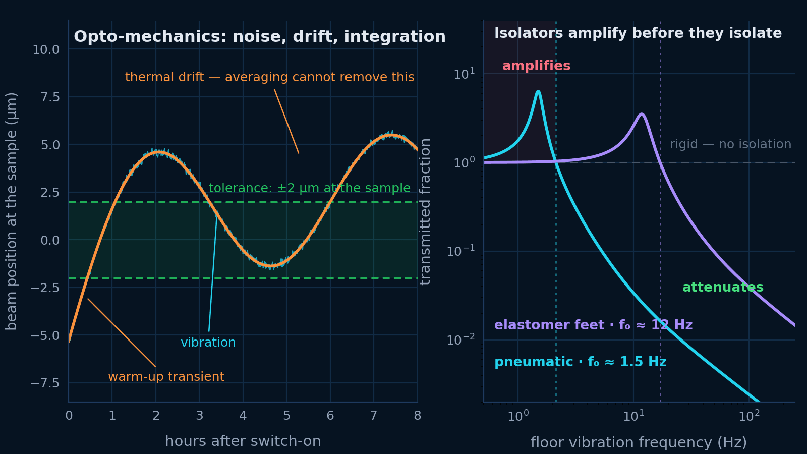
Building a stable opto-mechanical rig
Vibration, thermal drift and mechanical integration are one problem. Budget the motion at the sample, then specify the table, the isolation, the mounts and the beam height that budget asks for.
Open guide Photonics
How to fiber-couple a diode laser
Take an asymmetric diode beam from collimation through mode matching, SM/MM/PM fiber selection, alignment, polarization, feedback control, and long-term stability.
Open guide Precision engineering
Abbe error: what it is and how to calculate it
Angular error multiplied by offset — the largest geometric error in most precision machines, first order rather than second, and absent from every datasheet because half the product belongs to you.
Open guide Opto-mechanics
How to choose an optical table
Isolation only starts above √2 times the isolator natural frequency — below it a heavy table on stiff legs amplifies the floor. Where that corner sits is the specification; mass is not.
Open guideSpecify the rail
Send us the optical layout and we will send back the rod lengths.
Element spacings, apertures and where the adjustment has to live. That is enough to turn a ray diagram into a bill of materials that fits together the first time.