Tip/tilt around a sample plane
Correct sample tilt without translating the point of interest out of the field.
Opto-Mechanics · Ambient Piezo Stages - Lab goniometers
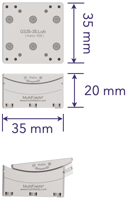
Lab goniometer stage; 35 x 35 mm footprint; +/-8 deg tilt; 35 mm rotation radius; 1 kg payload; 0.05 urad minimum incremental motion; co-pivot pair with GS35-55.Lab.
Datasheet (PDF) ↗Catalog context
GS35-35.Lab is listed in the Ambient Piezo Stages - Lab goniometers family. The local catalog record provides these first selection fields: Active axes: θX; Mass: 250 g; Travel range: ±8 °.
| Active axes | θX |
|---|---|
| Mass | 250 g |
| Travel range | ±8 ° |
| Max Driving Frequency | 20 kHz |
| Nominal Radius of Rotation | 35 mm |
| Max. Velocity | 3 °/s |
| Minimum Incremental Motion(Close-loop) | 2 urad |
| Unidirection Repeatability | ±10 urad |
| Max. Payload (horizontal mounting) | 1 kg |
| Holding Torque | 200 N·mm |
| Driving Torque | 70 N·mm |
| Sensor Type | Optical Sensor |
| Sensor Resolution | 0.05 urad |
| Controller | MC-Newton.S series |
Application context
Correct sample tilt without translating the point of interest out of the field.
Set the angle of incidence for reflectometry, ellipsometry and grazing-incidence work.
Square a mirror, grating or detector to the beam where a fixed pivot keeps the geometry intact.
System integration
Use these checks to connect GS35-35.Lab to the surrounding optical, mechanical and control system. Every value shown is taken from this model's own specification record.
Technical FAQ
Travel range: ±8 ° · Unidirection Repeatability: ±10 urad. Separate travel from resolution and both from repeatability. Repeatability is what an automated sequence actually depends on, and it is the figure most often absent from a headline specification.
Controller: MC-Newton.S series. Pair open-loop mechanics with the specified high-voltage or inertial driver, and closed-loop variants with the controller their capacitive, strain-gauge or encoder feedback requires. Matching connectors do not guarantee electrical compatibility.
Max. Payload (horizontal mounting): 1 kg. Check the load rating in the orientation you will use it — a vertical or cantilevered load is a moment, not a mass — and match the base to an M6 pattern on a 25 mm grid or a 1/4"-20 pattern on a 1 inch grid.
Specifying this part
Each goniometer tilts about a centre a fixed height above its own mounting surface, so a theta and phi pair share one virtual pivot. Get that height right against your sample plane or the beam walks as you tilt.
Most of the range is orderable as .HV (high vacuum), .UHV (ultra-high vacuum) or .NM (non-magnetic). The suffix changes materials, cabling and bake compatibility rather than the mechanics, so specify it against the chamber the stage will live in.
Full series comparison, controller pairing and mounting hardware on the ambient piezo stages overview, or work through the selection with the configurator.
Model selection
Compare GS35-35.Lab with the closest available models in the Ambient Piezo Stages - Lab goniometers family.
| Selection parameter | GS35-35.Lab (current) | GS35-55.Lab | GS65-77.Lab |
|---|---|---|---|
| Travel / adjustment | ±8 ° | ±8 ° | ±10 ° |
| Resolution / sensitivity | 0.05 urad | 0.03 urad | 0.03 urad |
| Mounting interface | 1 kg | 1 kg | 2 kg |
GS35-55.Lab
Lab goniometer stage; 35 x 35 mm footprint; +/-8 deg tilt; 55 mm rotation radius; 1 kg payload; 0.03 urad minimum incremental motion; co-pivot pair with GS35-35.Lab.
GS65-77.Lab
Lab goniometer stage; 70 x 70 mm footprint; +/-10 deg tilt; 77 mm rotation radius; 2 kg payload; 0.03 urad minimum incremental motion; co-pivot pair with GS65-97.Lab.
GS65-97.Lab
Lab goniometer stage; 70 x 70 mm footprint; +/-10 deg tilt; 97 mm rotation radius; 2 kg payload; 0.02 urad minimum incremental motion; co-pivot pair with GS65-77.Lab.
Before you specify
Engineering context for choosing this class of component, with the tradeoffs worked through on real specifications.
 Nanopositioning
Decide what to move — sample, objective or both — then turn field of view, stack depth, settling and synchronisation into stage specifications. Comparison tables, an acquisition-time calculator, three configurations and a purchasing checklist on documented objective scanners, clear-aperture XYZ stages and controllers.
Open guide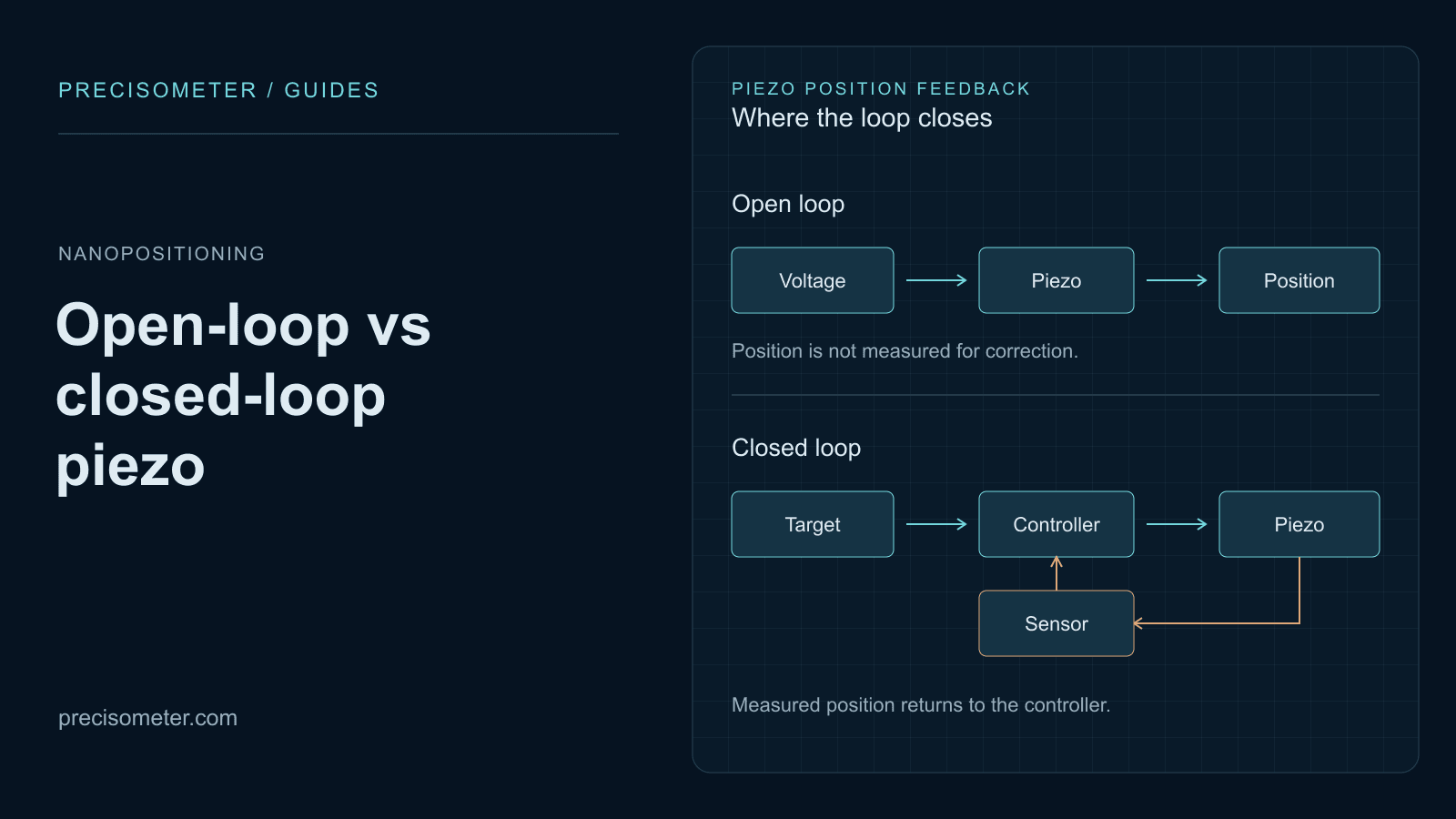 Nanopositioning
Why an open-loop piezo is wrong by 15 % of its travel, how creep grows with the logarithm of hold time, what strain-gauge and capacitive feedback actually fix — and the bandwidth and sensor noise a servo costs you in return.
Open guide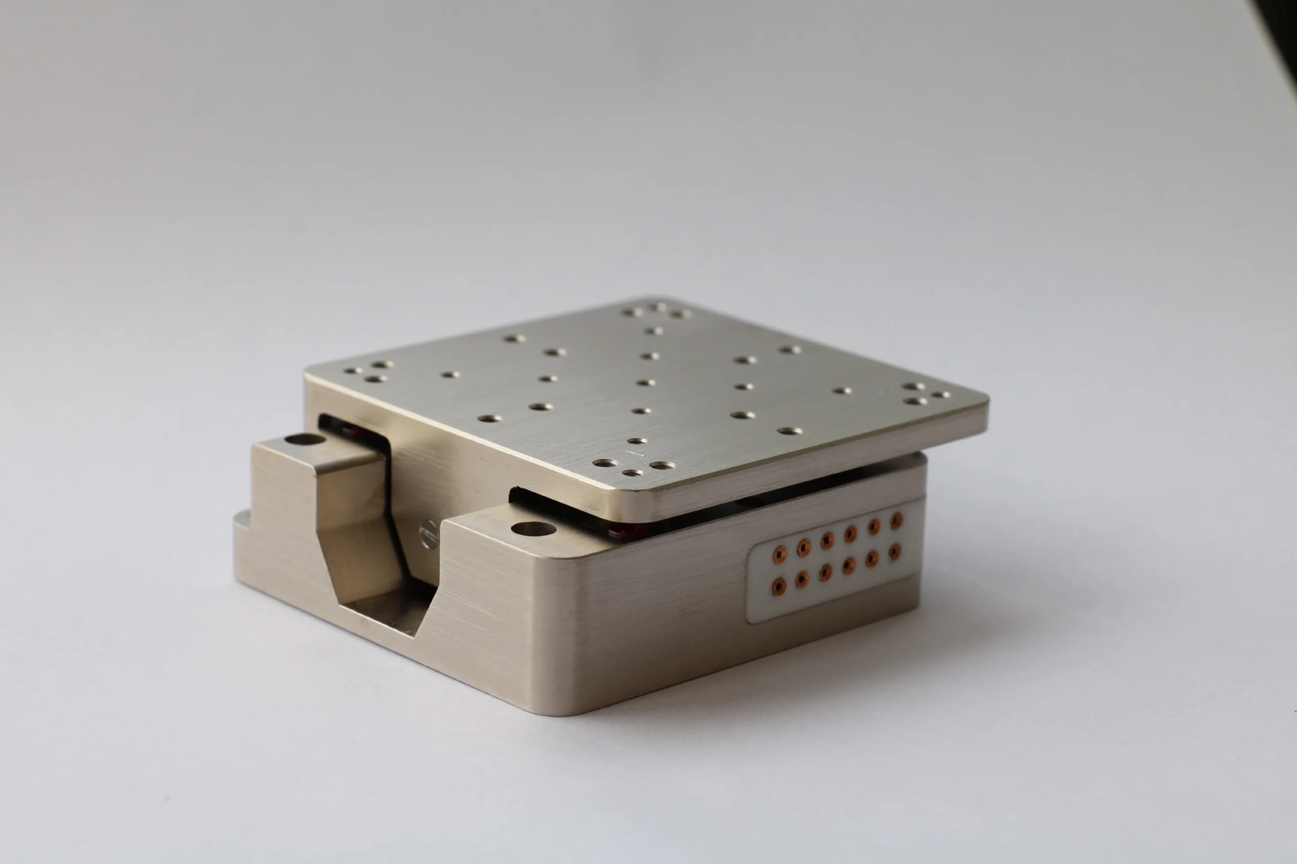 Nanopositioning
Piezo ceramic strains by one part in a thousand, so a 20 mm stack gives 20 µm. Every stage architecture is a different way around that limit — and each one wins a different experiment.
Open guide