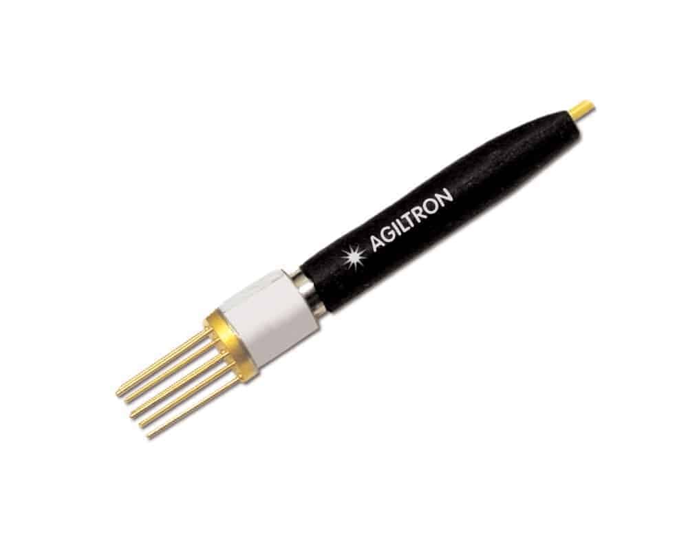
Transmitters & Receivers
1310/1550nm 10GHz Transceiver without TIA
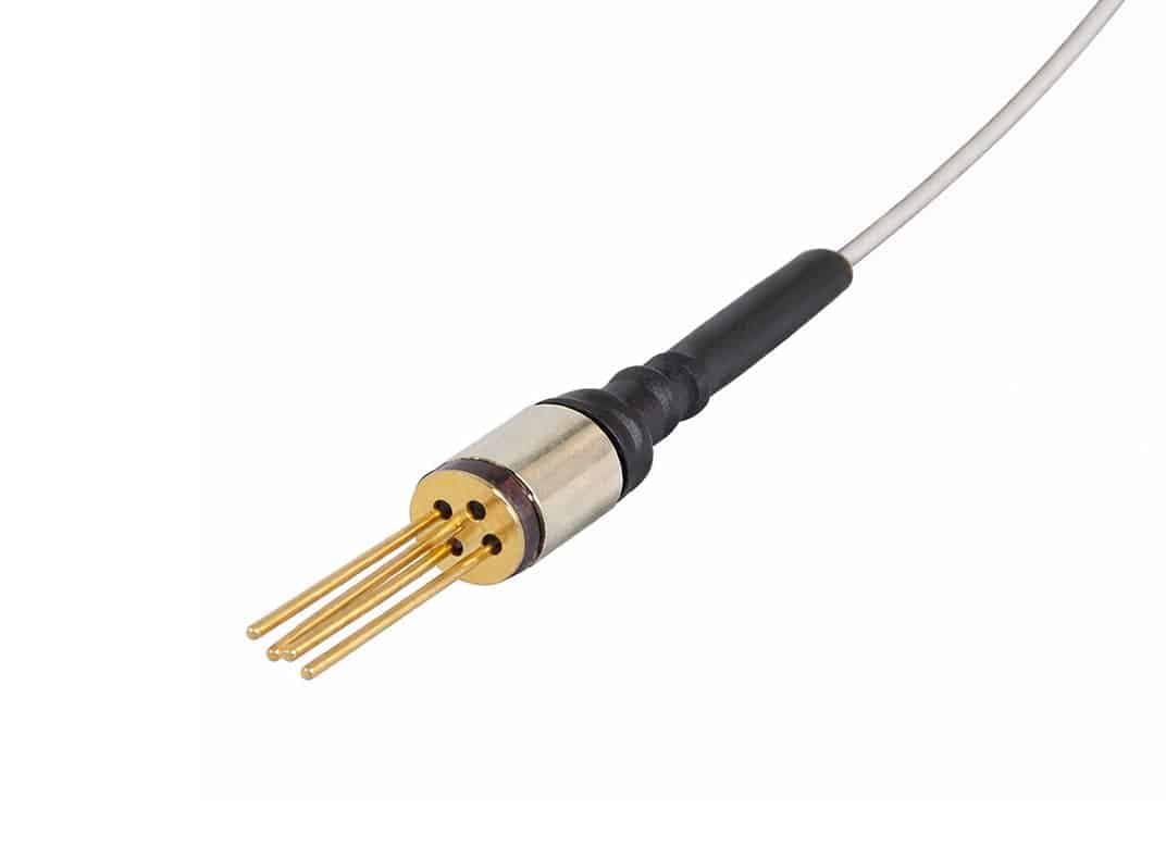
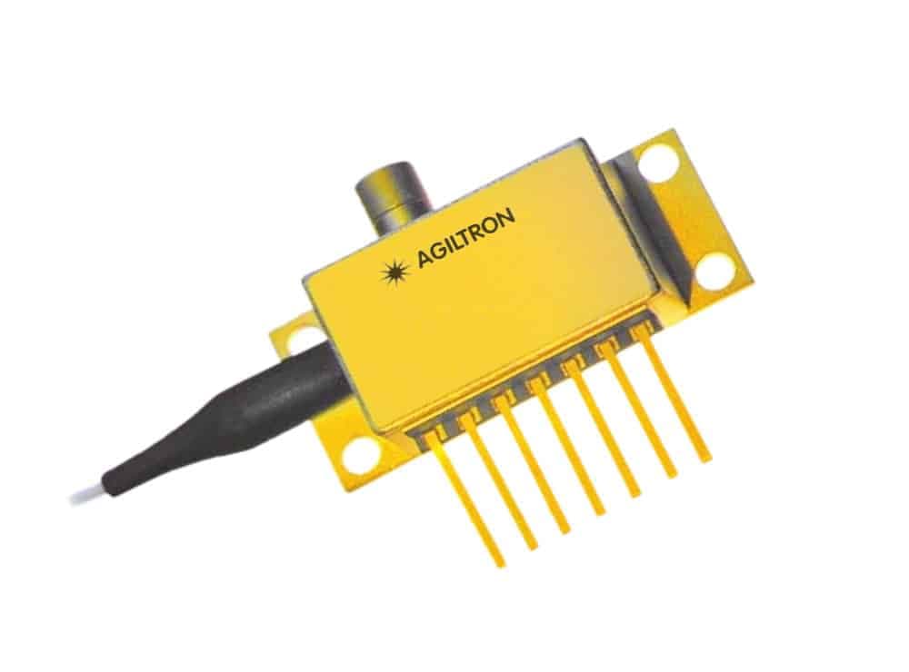
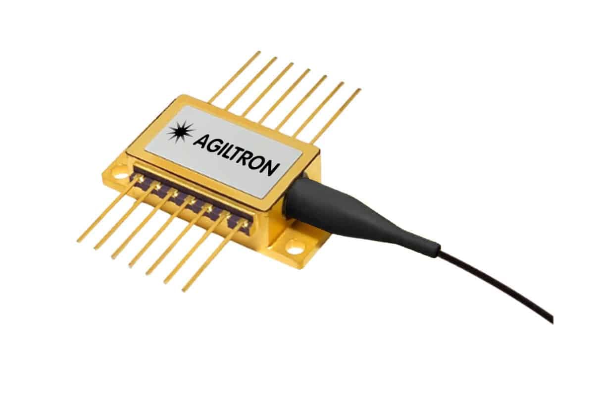
This series of Digital Transceivers is designed to provide an optical communication link between two points via a single strand of fiber with a data rate of up to 10GHz. Each transceiver consists of a DFB laser transmitter and a PIN detector receiver pair. They are available in wavelengths of 1310nm, 1490nm, and 1550nm, offering versatile wavelength division multiplexing (WDM) capability. For instance, bidirectional communication can be established using a single fiber link by employing two different wavelength transceivers along with matching WDM diplexer cable adaptors. One common setup involves pairing a 1310nm laser with a 1550nm detector at one end combined using a WDM diplexer, and a 1550nm laser with a 1310nm detector at the other end combined by a diplexer.
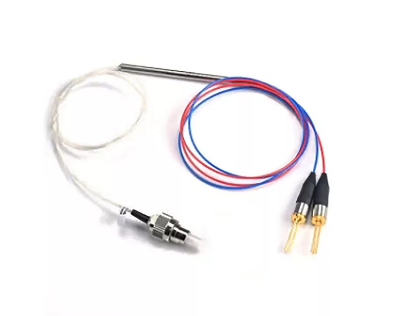
Configuration options
Build & quote
Configure the options below and add your exact build to the enquiry — we confirm the part number and availability.
We confirm the exact part number for your configuration on enquiry.
Transmitter Wavelength: 1310nm · Receiver Wavelength: 1310nm · Speed: 1GHz · Driver: No · Package: Standard · Fiber Type: SM28 · Fiber Buffer: 0.9mm Tube · Fiber Length: Standard · Connector: None
System integration
Integration and compatibility
Use these checks to connect 1310/1550nm 10GHz Transceiver without TIA to the surrounding optical, mechanical and control system. Every value shown is taken from this model's own specification record.
- Optical interface and fiber
- Fiber Type: SM28, 60.2/125, 50/125 · Fiber Buffer: 0.9mm Tube, 3mm Tube
- Specify connector polish and fiber architecture together. FC/PC, FC/APC and SMA interfaces, and single-mode, multimode and polarization-maintaining fibers, impose different return-loss, mode-field and alignment requirements.
- Wavelength and loss budget
- Transmitter Wavelength: 1310nm, 1550nm, 1490nm · Receiver Wavelength: 1310nm, 1550nm, 1490nm
- Check the Transmitters & Receivers passband, insertion loss, return loss and power handling at the actual source wavelength; a nominal telecom-band label is not a substitute for the configured range.
- Control interface
- Driver: No, Yes
- Match supply voltage, analog or digital command range, connector pinout and default optical state to the instrument interlock. Confirm the unpowered state explicitly — it decides what happens to the link on a power failure.
Technical FAQ
Integration questions for 1310/1550nm 10GHz Transceiver without TIA
Which fiber and connector does the 1310/1550nm 10GHz Transceiver without TIA use?
Fiber Type: SM28, 60.2/125, 50/125 · Fiber Buffer: 0.9mm Tube, 3mm Tube. Specify connector polish and fiber architecture together. FC/PC, FC/APC and SMA interfaces, and single-mode, multimode and polarization-maintaining fibers, impose different return-loss, mode-field and alignment requirements.
How should the 1310/1550nm 10GHz Transceiver without TIA be included in an optical power budget?
Transmitter Wavelength: 1310nm, 1550nm, 1490nm · Receiver Wavelength: 1310nm, 1550nm, 1490nm. Check the Transmitters & Receivers passband, insertion loss, return loss and power handling at the actual source wavelength; a nominal telecom-band label is not a substitute for the configured range.
Does the 1310/1550nm 10GHz Transceiver without TIA require a controller?
Driver: No, Yes. Match supply voltage, analog or digital command range, connector pinout and default optical state to the instrument interlock. Confirm the unpowered state explicitly — it decides what happens to the link on a power failure.
Need this configured?
Share your wavelength, fiber type, connector, power handling and control requirements and we will qualify the matching configuration and part number.
Model selection
Nearby series comparison
Compare 1310/1550nm 10GHz Transceiver without TIA with the closest available models in the Transmitters & Receivers family.
| Selection parameter | 1310/1550nm 10GHz Transceiver without TIA (current) | 12GHz Fiber Optical Amplified Photodetector / Photoreceiver |
|---|---|---|
| Wavelength range | 1310nm, 1550nm, 1490nm | 1200-1600nm |
| Fiber type | SM28, 60.2/125, 50/125 | — |
| Connector / control | None, FC/APC, Special | FC/PC, FC/APC, Special |