Back to Home
Fiber for Laser Coupling

Laser components & accessories

Fiber for Laser Coupling

Optical Fiber Optical Fiber can supply specialty optical fiber for laser coupling. Our products include single-mode fiber, multi-mode fiber, polarization maintaining fiber, liquid light fiber and fiber with pigtailed GRIN lens collimators for all our existing laser modules from visible to near IR transmission .

Single-mode fiber/ Fiber combinerMultimode fiber (SMA905 or FC/PC connector )
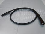
FC/PC or FC/APC connector. Single-mode fiber for core diameter of 2.5-10 um. Available for 400nm~1550 nm. Fiber splitter available for 532 nm.Multimode fiber for core diameter of 50 um, 100 um, 200 um, 400 um, 600 um, 800 um, 1000 um. Support more than one propagation mode.
Polarization maintaining fiberLiquid light fiber
Polarization maintaining fiber is available for wavelengths from 400 nm ~1550 nm.Liquid light fiber for core diameter of 3 mm, 5 mm, 8 mm, 10 mm.
Fiber with pigtailed GRIN lens collimatorsFiber with even beam spot
Diameter 1.8 mm clear aperture. Coupled to standard 62.5/ 200/ 400um fibers.Even square beam spot and even round beam spot are available on request.
Note: Standard fiber length is 1 m, other core diameters and lengths are available on requests.
Accessories for laser coupling
Fiber optic collimatorFiber Coupler
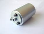
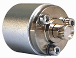
Used to shape the beam after fiber, FC or SMA connector optional. Good spot uniformity Adjustable focus optional Customization availablecan provide fiber coupler for all our existing lasers, SM/MM fiber type optional. The coupler is designed to connect the fiber and laser to improve fiber coupling efficiency
Fiber beam combinerFiber Holder
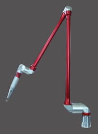
Designed for combining 4, 3, 2 fiber beam into 1 fiber (single-mode or multimode) output.Threaded hole: M6 Thread hole spacing: 50 mm Height: 30cm, 60cm optional Base size: 30cm* 30cm
Part No.Full fan Angle (α°)Line width at 2m location (mm)Material
FLG##80 °, 114°7-8BK7

Application context

Why this design is used

Application fit depends on the ordered configuration; catalog values are separated from fields that still require confirmation.

Laser delivery

Fiber for Laser Coupling: Mode-field, NA, connector polish and bend radius determine coupling efficiency, back-reflection and delivered beam quality.

Fiber-optic instrumentation

Fiber for Laser Coupling: Stable insertion loss and known polarization behavior keep calibration valid when sources, switches and detectors are interconnected.

Engineering reference

Specify Fiber for Laser Coupling from the interfaces inward

Fiber for Laser Coupling is a configurable fiber-optic interconnect in the Laser components and accessories family. The final part number should be released only after the optical, mechanical, electrical and environmental fields below are matched to the intended instrument.

A fiber interconnect is an optical component with modal, polarization and reflection behavior. Fiber construction, connector geometry and termination quality must match the source and receiving optics; identical connector shells do not imply optical compatibility.

Selection guidance describes the engineering fields that must be checked. It does not assign an option-dependent value that is absent from the catalog record.

Configuration fields to confirm

Fiber architecture
Specify single-mode, multimode, PM or specialty fiber, including core, NA and mode-field diameter.
Wavelength range
Confirm attenuation, mode guidance and coating suitability across the operating band.
Connector termination
Define FC/PC, FC/APC, SMA905 or other interfaces at both ends and key orientation for PM fiber.
Length and routing
State finished length, minimum bend radius, jacket and strain-relief requirements.
Optical performance
Set insertion loss, return loss, polarization extinction and power-handling limits.
Environment
Confirm temperature, vacuum, radiation, humidity or flex-cycle requirements for the installed route.

Qualification sequence

  1. 1Define the measurement objective and the performance limit that Fiber for Laser Coupling must satisfy.
  2. 2Freeze wavelength, mechanical, fiber and electrical interfaces before selecting option codes.
  3. 3Check loss, noise, heat, motion or vibration contributions in the complete system budget.
  4. 4Confirm the final drawing, pinout, environmental suffix and acceptance test with the quotation.

Technical FAQ

Configuration questions for Fiber for Laser Coupling

What must be specified before ordering Fiber for Laser Coupling?

Confirm fiber architecture, wavelength range, connector termination, length and routing, optical performance, and environment. These fields are coupled, so the final part number should be checked against the complete instrument rather than selected from the model name alone.

How should Fiber for Laser Coupling be integrated into the system?

A fiber interconnect is an optical component with modal, polarization and reflection behavior. Fiber construction, connector geometry and termination quality must match the source and receiving optics; identical connector shells do not imply optical compatibility. Freeze the optical, mechanical and electrical interfaces before releasing the surrounding assembly.

Which documentation should be approved for Fiber for Laser Coupling?

Approve the configuration-specific specification, mechanical drawing, connector or pinout definition, environmental suffix and acceptance-test limits supplied with the quotation. Any field absent from the local record remains a confirmation item, not an assumed capability.