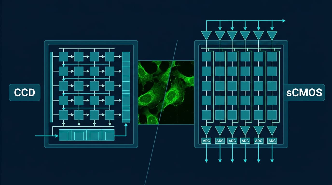
Fluorescence Imaging Guide
sCMOS vs CCD for Fluorescence Microscopy
In fluorescence imaging, every photon counts. The detector you choose determines whether dim structures emerge from the noise floor or vanish in it — and whether your cells survive the illumination.
Read Noise Decides
At < 20 photons/pixel — the typical fluorescence regime — read noise determines whether signal is visible. sCMOS wins by 10–30×.
Speed Without Penalty
sCMOS delivers 100+ fps without increasing noise. CCD doubles read noise every time you double the pixel clock.
Phototoxicity Savings
Lower read noise → less excitation light required → less photobleaching and reactive oxygen species → longer live-cell viability.
Why this guide exists
Fluorescence microscopy makes the detector choice simple — and critical.
Fluorescence imaging operates in one of the most photon-starved regimes in scientific imaging. Typical widefield fluorescence delivers 10–1 000 photons per pixel per frame. At this signal level, the detector’s read noise floor is the single largest controllable factor in image quality.
Our companion guide CCD vs CMOS: Readout Architectures & Physics explains the underlying silicon physics. This guide translates those physics into practical fluorescence microscopy decisions: which sensor technology, what specifications matter, and which cameras from our catalog to consider.
Physics-Based
SNR equations connect sensor specs directly to fluorescence image quality.
Technique-Specific
Widefield, TIRF, STORM, light-sheet, calcium imaging — each has different demands.
Real Specifications
Every number comes from our catalog datasheets, not marketing claims.
1 · The fluorescence challenge
Why fluorescence is the hardest photon budget in optical microscopy.
Photon Starvation
Fluorescence microscopy collects emission photons from fluorophores excited by an external light source. The fluorescence signal is inherently weak: fluorophores have limited quantum yields (typically 0.1–0.9), absorption cross-sections are small (~10⁻¹⁶ cm²), and emitted photons radiate isotropically — only a fraction is captured by the objective (collected solid angle depends on NA²).
The result: most fluorescence microscopy operates with 10–1 000 photons per pixel per frame, placing the experiment squarely in the read-noise-limited regime.
Phototoxicity Budget
You cannot simply increase excitation power to compensate for low signal. Excitation light generates reactive oxygen species (ROS) that damage cellular membranes, organelles, and DNA. Fluorophores themselves undergo irreversible photochemical destruction (photobleaching) after emitting a finite number of photons (~10⁵ for typical organic dyes).
A camera that extracts more information per excitation photon — through lower read noise and higher QE — directly extends the useful imaging duration and reduces biological perturbation.
2 · sCMOS vs CCD specification comparison
Seven specifications that determine fluorescence image quality.
Each row traces a specification back to the physical readout architecture difference between CCD and sCMOS.
Read Noise
4–30 e⁻ rms (cooled full-frame CCD at slow scan) — rises sharply with pixel clock rate.
< 1.0 e⁻ rms (back-illuminated sCMOS in HDR mode, e.g. sMAX04BM at 0.97 e⁻) — maintained at full speed.
sCMOSQuantum Efficiency (Peak)
90–95% (back-illuminated deep-depletion CCD, e.g. E2V spectroscopy-grade).
95% @ 560 nm (BSI sCMOS, e.g. GSENSE2020BSI). Front-illuminated sCMOS: 60–75%.
TieFrame Rate (Full Frame)
1–10 fps typical for scientific-grade megapixel CCDs. Faster rates drastically increase read noise.
40–100+ fps at full resolution. sMAX04BM delivers 108 fps full frame via Camera Link.
sCMOSFull-Well Capacity
> 100 ke⁻ (area CCDs) to > 400 ke⁻ (linear spectroscopy CCDs like sCCD01AM at 459 ke⁻).
30–54 ke⁻ typical per pixel. In-pixel transistors limit charge storage area.
CCDDynamic Range (Single Frame)
~14 bit single-gain. Limited by read noise floor at low signal.
Up to 16-bit HDR from dual-gain column amplifiers that digitize HCG and LCG simultaneously.
sCMOSFixed-Pattern Noise (FPN)
Virtually zero: single output amplifier processes all pixels identically.
Present due to millions of distinct in-pixel transistors. Corrected by factory DSNU/PRNU calibration maps.
CCDShutter
Inherent global shutter (mechanical or electronic). All pixels integrate light simultaneously.
Rolling shutter by default (4T pixel). Global shutter CMOS requires 5T/6T pixel — trades fill factor.
CCD3 · SNR regime analysis
Where you are on the photon curve determines which sensor wins.
Signal-to-noise ratio in a camera pixel is governed by three noise sources: read noise (σread), shot noise (√S), and dark current noise (√D). In fluorescence microscopy with cooled sensors, dark current is negligible, leaving:
SNR = S / √(S + σ²read)
Read-Noise Limited (< 20 photons/px)
SNR ≈ S / σ_read
When collected signal is below ~20 photons per pixel, read noise dominates the denominator. A camera with 0.9 e⁻ read noise delivers 10× higher SNR than one with 9 e⁻ at 10 photons signal.
Sub-electron sCMOS read noise makes dim fluorescence visible that CCD would lose entirely.
Shot-Noise Limited (100–10 000 photons/px)
SNR ≈ √S
At moderate-to-high photon counts, Poisson photon shot noise (√S) overwhelms read noise. Both sensor types deliver similar SNR — but sCMOS still wins on speed and HDR dynamic range.
Sensor choice is decided by frame rate, field of view, and interface bandwidth rather than noise floor.
Full-Well Limited (> 50 000 photons/px)
SNR limited by well capacity
When a pixel saturates before sufficient integration time, full-well capacity limits dynamic range. CCD pixels with > 400 ke⁻ store 10× more charge than typical sCMOS pixels.
Quantitative fluorescence spectroscopy or very bright specimens benefit from deep CCD charge wells.
4 · Technique-by-technique verdicts
Which sensor wins for each fluorescence microscopy modality.
Each technique operates in a different photon regime with different speed and noise requirements.
Widefield Epi-Fluorescence
10–1 000YesNosCMOSSub-electron read noise preserves dim structures that CCD read noise floor would bury. Speed is secondary.
Confocal (Laser Scanning)
5–100 per dwellYesNoPMT / sCMOSPoint detectors (PMTs, GaAsP) dominate confocal. Camera-based spinning-disk confocal benefits from sCMOS.
Light-Sheet (SPIM / DSLM)
50–5 000YesYessCMOSsCMOS rolling shutter naturally synchronizes with the sweeping light sheet. Requires 50+ fps for volumetric stacks.
TIRF
10–500YesYessCMOSSingle-molecule TIRF demands sub-electron noise and high QE to resolve individual fluorophore emissions.
STORM / PALM (SMLM)
500–5 000 per localizationNoYessCMOSLocalization precision is photon-limited, not noise-limited. sCMOS speed (100+ fps) is critical for acquiring 10⁴–10⁵ frames.
FRAP / Photoactivation
100–10 000NoYessCMOSRecovery kinetics require millisecond temporal resolution — only sCMOS delivers the frame rate.
Calcium / Voltage Imaging
100–10 000NoYessCMOSNeural transients occur in 1–10 ms. 500+ fps ROI readout captures dynamics CCD cannot access.
Fluorescence Spectroscopy (Long Integration)
10 000–100 000+NoNoCCDMassive full-well capacity (> 400 ke⁻), zero FPN, and single-amplifier uniformity outperform sCMOS at high signal.
5 · Phototoxicity & illumination dose
A better detector is a gentler experiment.
The Illumination–Noise Tradeoff
To maintain a target SNR, the required photon signal per pixel is:
S = ½ × (SNR² + SNR × √(SNR² + 4σ²read))
At SNR = 5 (a reasonable detection threshold):
- sCMOS (σ = 0.9 e⁻): S ≈ 26 photons needed per pixel
- CCD (σ = 10 e⁻): S ≈ 125 photons needed per pixel
- CCD (σ = 25 e⁻): S ≈ 650 photons needed per pixel
Biological Consequences
The illumination reduction enabled by sCMOS read noise translates directly into measurable biological benefits:
- Photobleaching rate: Scales linearly with illumination intensity. 5× less light → 5× more frames before fluorophore destruction.
- Reactive oxygen species: ROS generation is proportional to absorbed photons. Reduced dose directly reduces oxidative stress on living cells.
- Time-lapse duration: Live-cell imaging sessions that last hours with sCMOS may last minutes with CCD at equivalent SNR, before phototoxic effects alter cell behavior.
- Z-stack depth: Each slice contributes to the cumulative photon dose. Gentler per-slice illumination allows deeper volumetric imaging.
6 · What about EMCCD?
Electron multiplication solved read noise — but introduced new problems.
On-Chip Electron Multiplication
EMCCD (Electron Multiplying CCD) adds a gain register after the standard CCD shift register. High clock voltages in the multiplication register produce impact ionization, amplifying the signal by 100–1 000× before the output amplifier. This makes the effective read noise negligible compared to the amplified signal.
Excess Noise Factor √2
The stochastic nature of impact ionization means the multiplication gain is not deterministic — it follows an exponential distribution. This introduces an excess noise factor (ENF) of √2 ≈ 1.41, which is mathematically equivalent to halving the quantum efficiency.
- A 90% QE EMCCD behaves as if it has 45% effective QE in the shot-noise-limited regime.
- sCMOS achieves true sub-electron read noise without any multiplication penalty — QE is preserved at 95%.
- EMCCD multiplication gain degrades over time (10⁹ clock cycles), requiring periodic recalibration.
7 · Pixel size & Nyquist sampling
Pixel size determines spatial resolution and photon collection — it is not just a number.
≥ 2.3 Pixels per Airy Disk
Nyquist sampling requires at least 2 camera pixels to span one resolution element. In practice, 2.3× oversampling preserves information for deconvolution and quantitative analysis. For a 60× / 1.4 NA objective imaging GFP (λ = 509 nm), the Airy disk at the camera is ~15 µm → ideal pixel ≈ 6.5 µm.
Larger Pixels Collect More Light
At the same irradiance, a 11 µm pixel collects ~2.9× more photons than a 6.5 µm pixel (proportional to area). In photon-starved fluorescence, this can shift the SNR regime from read-noise-limited to shot-noise-limited. Balance against spatial resolution requirements.
Effective Fill Factor
CCD pixels have ~100% fill factor (no in-pixel transistors). Front-illuminated sCMOS has 50–70% fill factor due to transistor wiring; micro-lenses recover most of this. Back-illuminated sCMOS achieves ~100% fill factor and 95% peak QE — eliminating the historical CCD advantage.
Practical Pixel Matching for Common Objectives
| Objective | NA | Airy Disk (GFP, camera plane) | Ideal Pixel Size | Matched Camera |
|---|---|---|---|---|
| 100× Oil | 1.4 | ~22 µm | ~11 µm | sMAX04BM (11 µm) |
| 60× Oil | 1.4 | ~13 µm | ~6.5 µm | 6.5 µm sCMOS (common) |
| 40× Air | 0.95 | ~13 µm | ~6.5 µm | 6.5 µm sCMOS |
| 20× Air | 0.75 | ~8 µm | ~4 µm | Small-pixel sCMOS or 2× relay |
8 · Honest verdict for fluorescence
sCMOS has won fluorescence microscopy. CCD retains a narrow niche.
The physics is unambiguous: in the read-noise-limited regime where fluorescence lives, sub-electron sCMOS noise and 100+ fps frame rates are transformative advantages CCD cannot match.
Choose sCMOS When
- Widefield, TIRF, or light-sheet fluorescence: Sub-electron read noise is the defining advantage.
- Live-cell time-lapse: Lower illumination dose extends cell viability by hours.
- STORM / PALM / localization microscopy: 100+ fps speed is essential for practical acquisition times.
- Calcium / voltage imaging: Millisecond dynamics require 200–1 000 fps (ROI readout).
- Any new fluorescence instrument: Unless the specific CCD cases below apply, sCMOS is the default choice in 2026.
Choose CCD When
- Fluorescence spectroscopy with long integration: Full-well capacity > 400 ke⁻ and zero FPN suit high-signal spectral line work.
- Quantitative photometry requiring raw uniformity: Single-amplifier CCD preserves uncalibrated pixel-to-pixel linearity.
- Pulsed excitation with global shutter requirement: If timing demands true simultaneous exposure and global-shutter sCMOS fill-factor penalty is unacceptable.
9 · Recommended cameras
sCMOS cameras matched to fluorescence microscopy.
Every specification quoted below is drawn directly from our catalog datasheets. All three feature back-illuminated sCMOS sensors optimized for low-light fluorescence.
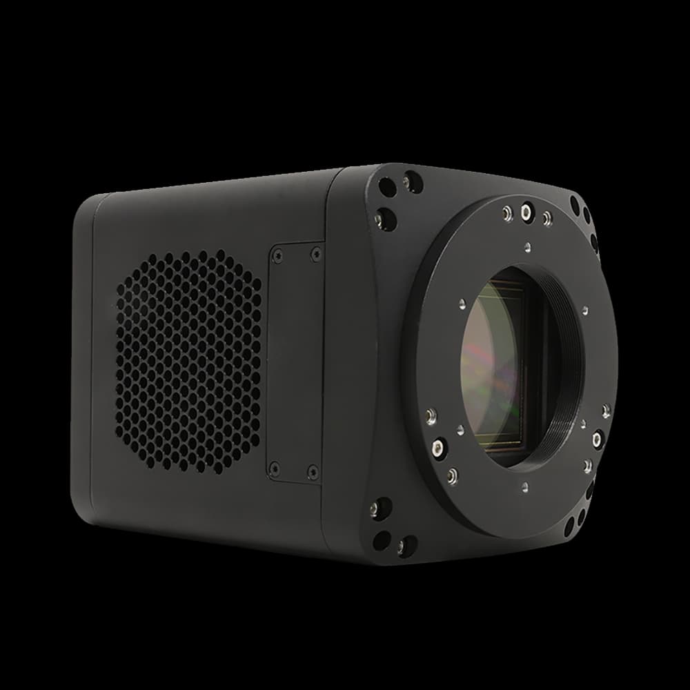
sMAX04BM-CL100
GSENSE2020BSI 4.2 MP sensor. 0.97 e⁻ rms read noise in HDR 11HL mode, 95% peak QE @ 560 nm, 108 fps full frame over Camera Link. The reference platform for modern fluorescence microscopy.
sMAX16BM-U3-CL
36.9 mm square format GSENSE4040BSI sensor. 90% peak QE @ 550 nm, 9 µm pixels. Replaces multi-field tiling with single-frame whole-FOV acquisition for large-area fluorescence.
sMAX04BM
Same GSENSE2020BSI sensor as sMAX04BM-CL100 but with USB 3.0 interface. 1.0 e⁻ rms read noise, 95% peak QE. Ideal when Camera Link infrastructure is not available.
10 · Related guides
Dive deeper into camera physics and fluorescence system design.
CCD vs CMOS: Readout architectures & physics
The underlying silicon physics: charge transfer, column ADCs, rolling shutter, FPN, and blooming explained at the device level.
Open guide sCMOS SelectionHow to select an sCMOS camera
Compare quantum efficiency, read-noise modes, pixel size, and optical sampling across real sMAX specifications.
Open guide Decision FrameworkChoosing a scientific camera
The general buyer’s workflow: photon budget, noise regime, shutter, and interface bandwidth checks.
Open guide11 · Common questions
Frequently asked questions about sCMOS vs CCD for fluorescence.
Is sCMOS always better than CCD for fluorescence microscopy?+
For the vast majority of fluorescence imaging — widefield, TIRF, light-sheet, STORM/PALM, live-cell, calcium imaging — sCMOS is superior because sub-electron read noise preserves weak fluorescence signals and 100+ fps frame rates capture fast dynamics. CCD retains advantages only in niche applications requiring massive full-well capacity (> 400 ke⁻ for spectroscopy) or inherent global shutter without pixel fill-factor penalty.
How does read noise affect fluorescence image quality?+
Read noise adds a fixed uncertainty to every pixel value regardless of signal. At 10 photons per pixel, a camera with 10 e⁻ read noise has SNR ≈ 1.0 (signal buried in noise), while 0.9 e⁻ read noise gives SNR ≈ 10. In fluorescence microscopy where excitation light must be minimized to avoid photobleaching, the read-noise floor directly determines whether dim structures are visible.
Why does sCMOS rolling shutter matter in fluorescence?+
In rolling shutter mode, each row begins and ends its exposure at a slightly different time. For static or slowly changing fluorescence specimens, this is invisible. For fast events (calcium transients, flowing cells) or pulsed laser illumination, the temporal skew across the frame can introduce spatial distortion. However, rolling shutter naturally synchronizes with light-sheet microscopy because the illuminated sheet sweeps through the sample row-by-row, matching the camera readout.
Can CCD match sCMOS speed by reading out faster?+
CCD read noise scales directly with pixel clock bandwidth: doubling the readout speed roughly doubles the read noise, because the single output amplifier must process signals at higher bandwidth. An EMCCD can use electron multiplication to overcome this, but EMCCD introduces multiplicative excess noise (noise factor √2 ≈ 1.4×) that degrades SNR at moderate signal levels. sCMOS column-parallel readout is inherently fast and quiet simultaneously.
What about EMCCD — is it still relevant for fluorescence?+
EMCCD uses an on-chip electron multiplication register to amplify signal before the read amplifier, effectively reducing the read noise to < 1 e⁻ — but at the cost of a multiplicative excess noise factor of √2 (≈ 1.41×). This means the effective QE is halved in shot-noise-limited regimes. Back-illuminated sCMOS achieves true sub-electron read noise without multiplication, preserving full QE. EMCCD has been largely displaced by BSI sCMOS for quantitative fluorescence imaging since approximately 2018.
How does phototoxicity factor into the sCMOS vs CCD decision?+
A camera with lower read noise allows you to use less excitation light to achieve the same SNR. In live-cell fluorescence, excitation light generates reactive oxygen species that damage cells (phototoxicity) and accelerate fluorophore destruction (photobleaching). The 10–30× read noise advantage of sCMOS over CCD translates directly into 10–30× less illumination required at the read-noise-limited boundary, extending cell viability and experiment duration.
What pixel size is best for fluorescence microscopy?+
Nyquist sampling requires at least 2 pixels per resolution element at the image plane. For a 100× / 1.4 NA objective imaging GFP (em. 509 nm), the Airy disk diameter at the sample is ~220 nm, projecting to ~22 µm at the camera. Optimal pixel size is 22/2 = 11 µm. With a 60× objective, optimal is ~6.6 µm. Most sCMOS cameras offer 6.5 µm pixels (ideal for 60× objectives) or 11 µm pixels (ideal for 100× objectives). The sMAX16BM has 9 µm pixels, suited to intermediate magnifications.