Pre-aligned optical axes
Four rods define the axis, so every element threaded onto them starts square and centred.
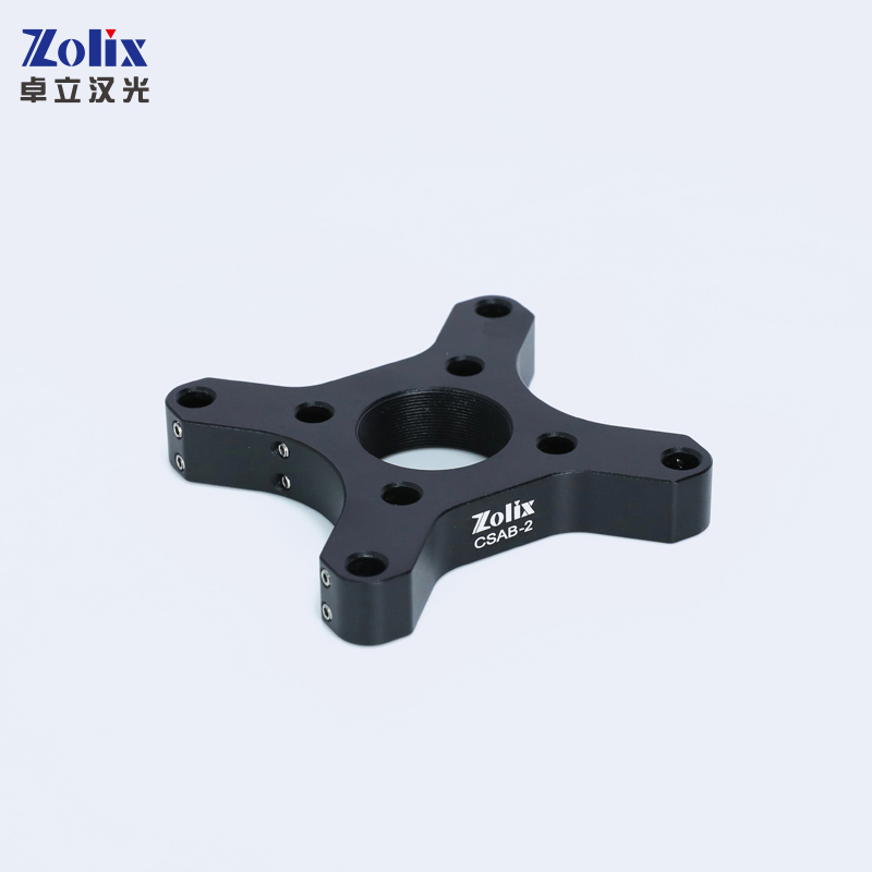
Cage Systems · Right-Angle Adapter Plates
Right-Angle Adapter Plates
Zolix’s right-angle adapter plates are designed to couple two 30 mm cage system at 90°, the front side of each adapter has flexuous clamps that can be slid onto two parallel cage rods.
Datasheet (PDF) ↗CAD Model (RAR) ↗Catalog context
CSAB-2 is listed as Right-Angle Adapter Plates in the Right-Angle Adapter Plates family. The local catalog record provides these first selection fields: Function: Mount a 30 mm cage system onto another 30 mm cage system at a right angle; Aperture: Ø23 mm.
| Function | Mount a 30 mm cage system onto another 30 mm cage system at a right angle |
|---|---|
| Aperture | Ø23 mm |
Application context
Application guidance is derived from the product family and tied to the model-specific selection fields above.
Four rods define the axis, so every element threaded onto them starts square and centred.
Build a relay, filter block or launch module that can be moved between setups intact.
Package an optical train into a rigid unit for OEM and portable instruments.
System integration
Use these checks to connect CSAB-2 to the surrounding optical, mechanical and control system. Every value shown is taken from this model's own specification record.
Technical FAQ
Aperture: Ø23 mm. Check diameter and thickness together. A holder that accepts the diameter can still fail to retain an optic that is thinner than its minimum, and clear aperture is normally smaller than the optic the mount holds.
Model selection
Compare CSAB-2 with the closest available models in the Right-Angle Adapter Plates family. Confirm option-dependent values on the final configuration before ordering.
| Selection parameter | CSAB-2 (current) | CSABV-2 | CSACS-4-40 |
|---|---|---|---|
| Optic accepted | Ø23 mm | Confirm for this model | Confirm for this model |
| Adjustment | Confirm for this model | Confirm for this model | Confirm for this model |
| Mounting interface | Confirm for this model | Confirm for this model | Confirm for this model |
| Material | Confirm for this model | Confirm for this model | Confirm for this model |
Before you specify
Engineering context for choosing this class of component, with the tradeoffs worked through on real specifications.
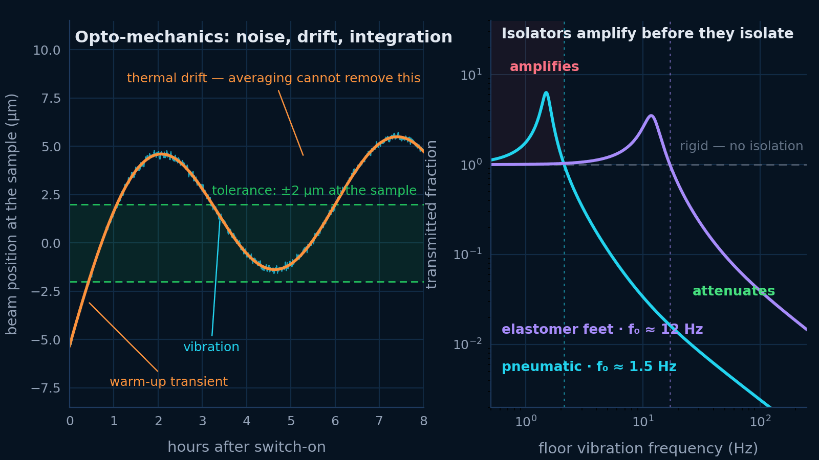 Opto-mechanics
Vibration, thermal drift and mechanical integration are one problem. Budget the motion at the sample, then specify the table, the isolation, the mounts and the beam height that budget asks for.
Open guide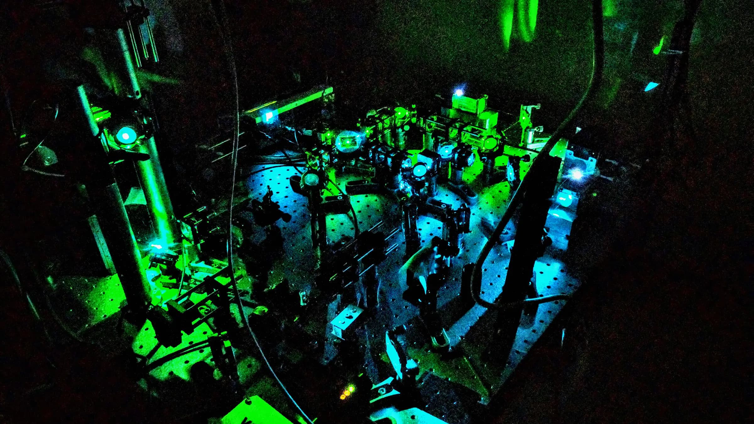 Optical microscopy
Design the trapping beam, objective, mechanics, imaging, QPD detection, calibration, and safety workflow as one instrument.
Open guide