Fine angular and linear adjustment
Fine-pitch screws convert a comfortable knob rotation into a few microns of travel.
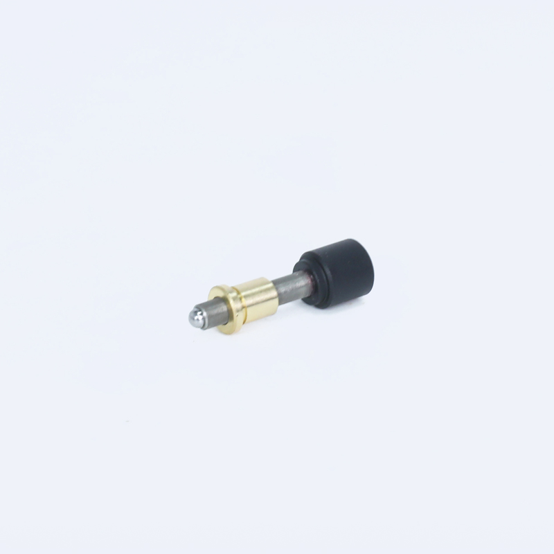
Adjustment Screws & Tools · NAFS Series Adjustment Screw
NAFS Series Adjustment Screw
Description: NAFS is based on ACFS series thread, we adopt 0.1mm/0.2mm pitch in this products to reach ultimate precision adjustment.
Datasheet (PDF) ↗CAD Model (RAR) ↗Catalog context
NAFS13-M4-0.1P is listed as NAFS Series Adjustment Screw in the NAFS Series Adjustment Screw family. The local catalog record provides these first selection fields: Model: NAFS13-M4-0.1P; Translation Range(mm): 13; Adjustment Screw and Pitch: M4×0.1.
| Model | NAFS13-M4-0.1P |
|---|---|
| Translation Range(mm) | 13 |
| Adjustment Screw and Pitch | M4×0.1 |
| Mounting Diameter(mm) | Ø6 |
| Mounting Length(mm) | 7 |
| Overall Length(mm) | 37 |
| Thumb Wheel Diameter(mm) | Ø9 |
Application context
Application guidance is derived from the product family and tied to the model-specific selection fields above.
Fine-pitch screws convert a comfortable knob rotation into a few microns of travel.
Raise the resolution of a mount already in service by changing only its adjusters.
Radial locking holds the setting once alignment is complete, through handling and thermal cycling.
System integration
Use these checks to connect NAFS13-M4-0.1P to the surrounding optical, mechanical and control system. Every value shown is taken from this model's own specification record.
Technical FAQ
NAFS13-M4-0.1P. Match the thread standard and hole pitch before ordering. Metric and imperial hardware interchange only through an adapter, and a thread that is nominally similar is not necessarily the same pitch.
Adjustment Screw and Pitch: M4×0.1. Adjuster pitch sets the sensitivity you can actually work at. Confirm whether the stated figure is a total range or a per-revolution increment, and whether the mechanism is locked after adjustment.
Model selection
Compare NAFS13-M4-0.1P with the closest available models in the NAFS Series Adjustment Screw family. Confirm option-dependent values on the final configuration before ordering.
| Selection parameter | NAFS13-M4-0.1P (current) | AUS25.4-3.0 | NAFS13-M4-0.2P |
|---|---|---|---|
| Optic accepted | Confirm for this model | Confirm for this model | Confirm for this model |
| Adjustment | M4×0.1 | M6×0.2 | M4×0.2 |
| Mounting interface | Ø6 | M9×0.5 | Ø6 |
| Material | Confirm for this model | Confirm for this model | Confirm for this model |
Before you specify
Engineering context for choosing this class of component, with the tradeoffs worked through on real specifications.
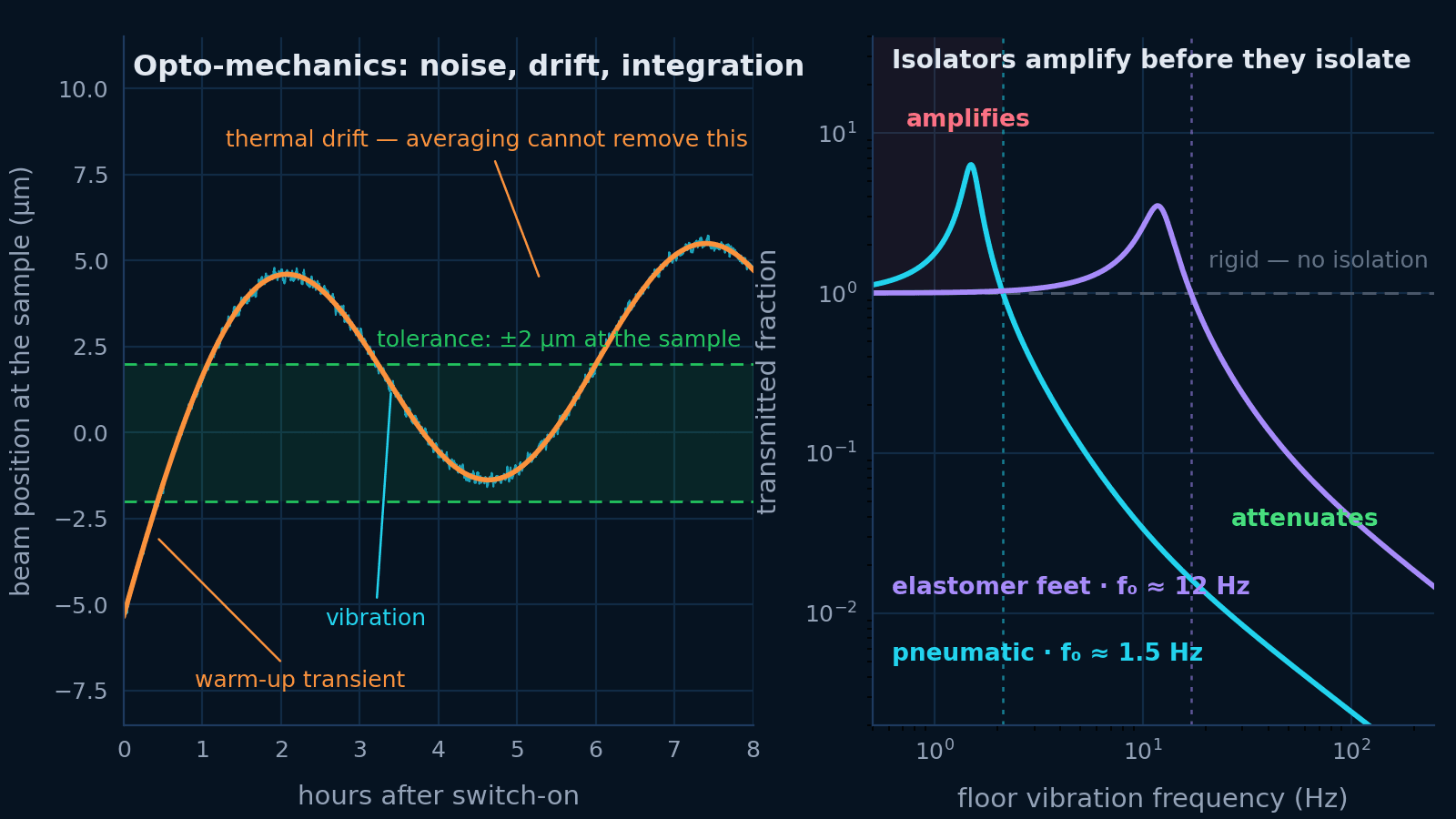 Opto-mechanics
Vibration, thermal drift and mechanical integration are one problem. Budget the motion at the sample, then specify the table, the isolation, the mounts and the beam height that budget asks for.
Open guide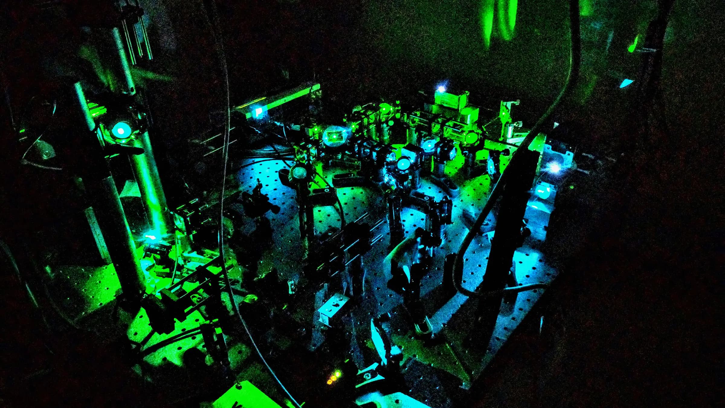 Optical microscopy
Design the trapping beam, objective, mechanics, imaging, QPD detection, calibration, and safety workflow as one instrument.
Open guide