Variable Optical Attenuators
MEMS Broadband Optical Attenuator – Fiber-Fiber™
The Fiber-Fiber™ series VOA is based on fiber-to-fiber direct coupling with a micro-electro-mechanical (MEMS) shutter in between. It eliminates the need for lens and optical coating, featuring low loss, ultra-broadband without altering fiber transmission character, high power, compact size, and easy drive. The current MEMS chips accommodate fiber with 3 to 105 mm core diameters. VOAs with fiber of larger diameters can be made with special chip fabrication run with an NRE charge. The Fiber-Fiber™ series VOA is compliant with the Telcordia 1209 and 1221 reliability standards. The VOA is driven by directly applying a low electrical voltage. The VOA is electrically a resistor load, has no polarity, and is electrostatically insensitive.
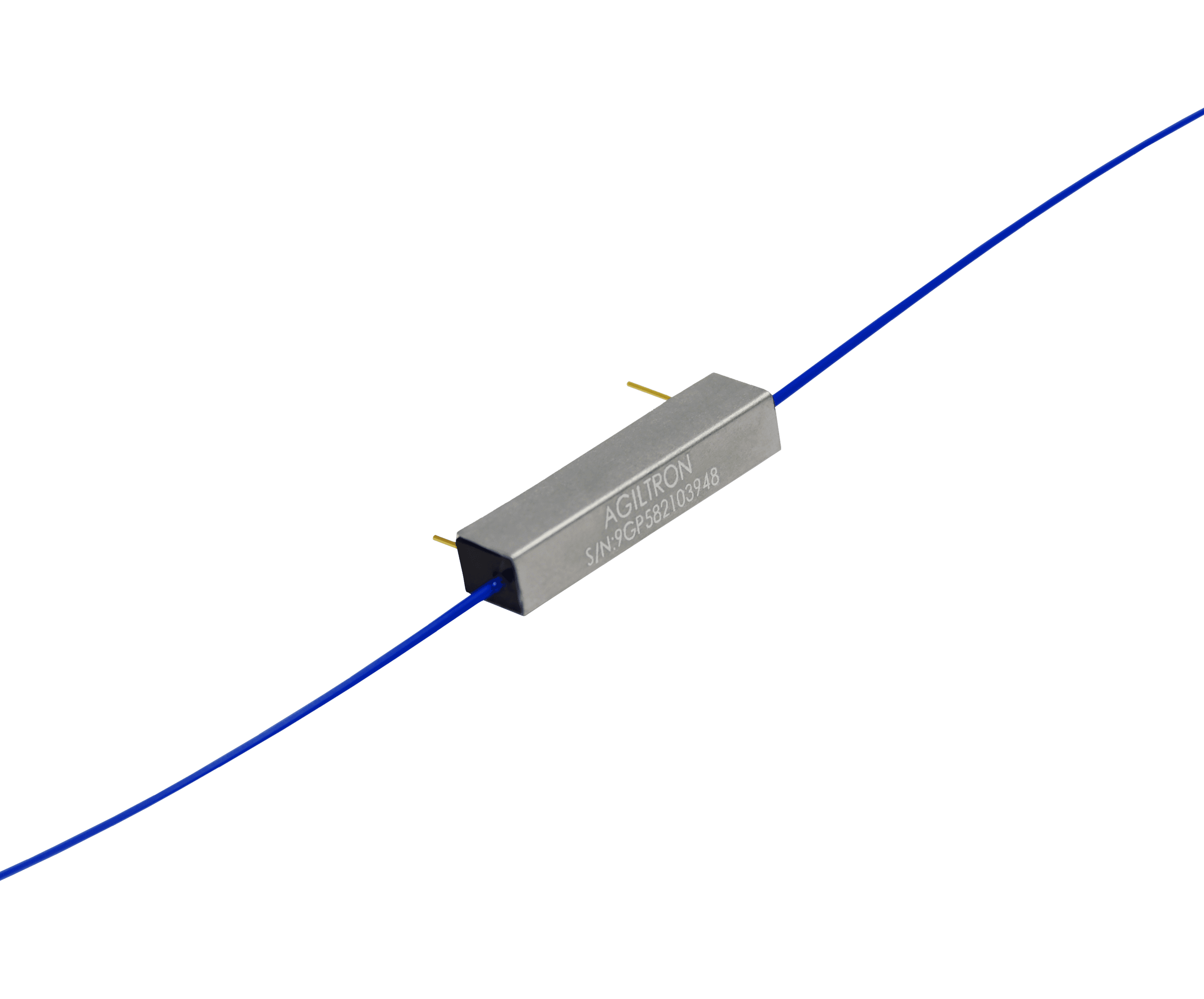
Specifications
MEMS Broadband Optical Attenuator – Fiber-Fiber™
| Fiber Type | SM400 | SM450 | SM600 | Hi780 | SM800 | Hi980 | Hi1060 | SM28 | SM1950 |
| Wavelength Range | 405 – 532 nm | 480 – 650 nm | 620 – 650 nm | 760 – 800 nm | 830 – 870 nm | 980 – 1550 nm | 960 – 1080 nm | 1020 – 1900 nm | 1.7 – 2.3 µm |
| Insertion Loss | <1 dB | <1 dB | ≤0.8 dB | ≤0.6 dB | ≤0.5 dB | ≤0.5 dB | ≤0.4 dB | ≤0.2 dB | ≤0.5 dB |
| Maximum Attenuation | 50 dB | 50 dB | 50 dB | 50 dB | 50 dB | 50 dB | 50 dB | 48 dB | 48 dB |
| Max Optical Power | 1mW | 5mW | 0.1W | 0.2W | 0.3W | 0.3W | 0.3W | 0.5W | 0.5W |
| Polarization DL | 0.2 dB@20dB | 0.2 dB@20dB | 0.2 dB@20dB | 0.2 dB@20dB | 0.2 dB@20dB | 0.2 dB@20dB | 0.2 dB@20dB | 0.2 dB@20dB | 0.2 dB@20dB |
| Return Loss | ≥35 dB | ≥35 dB | ≥35 dB | ≥35 dB | ≥35 dB | ≥35 dB | ≥35 dB | ≥35 dB | ≥35 dB |
| Operating Temperature | 40 to 80°C | 40 to 80°C | 40 to 80°C | 40 to 80°C | 40 to 80°C | 40 to 80°C | 40 to 80°C | 40 to 80°C | 40 to 80°C |
| Storage Temperature | 50 to 85°C | 50 to 85°C | 50 to 85°C | 50 to 85°C | 50 to 85°C | 50 to 85°C | 50 to 85°C | 50 to 85°C | 50 to 85°C |
| Fiber Type | PM405 | PM460 | PM630 | PM780 | PM850 | PM980 | PM1550 | PM1950 |
| Wavelength Range | 400 – 680 nm | 460 – 700 nm | 620 – 650 nm | 760 – 800 nm | 830 – 870 nm | 960 – 1080nm | 1260 – 1650nm | 1850 – 2200nm |
| Insertion Loss | ≤1.1 dB | ≤0.9 dB | ≤0.9 dB | ≤0.8 dB | ≤0.7 dB | ≤0.6 dB | ≤0.2 1dB | ≤0.8 dB |
| Max Attenuation | 50 dB | 50 dB | 50 dB | 50 dB | 50 dB | 35 dB | 35 dB | 70 dB |
| Extinction Ratio | >20 dB | >20 dB | >20 dB | >20 dB | >20 dB | >20 dB | >20 dB | >20 dB |
| Return Loss | ≥35 dB | ≥35 dB | ≥35 dB | ≥35 dB | ≥35 dB | ≥35 dB | ≥35 dB | ≥35 dB |
| Max Power | 1mW | 5mW | 0.1W | 0.2W | 0.3W | 0.3W | 0.5W | 0.5W |
| Operating Temperature | 40 to 80°C | 40 to 80°C | 40 to 80°C | 40 to 80°C | 40 to 80°C | 40 to 80°C | 40 to 80°C | 40 to 80°C |
| Storage Temperature | 50 to 90°C | 50 to 90°C | 50 to 90°C | 50 to 90°C | 50 to 90°C | 50 to 90°C | 50 to 90°C | 50 to 90°C |
| Fiber Type | GIF50 | GIF625 | FG50LGA | FG105LCA | FG10LDA |
| Wavelength Range | 800 – 1600 nm | 800 – 1600 nm | 400 – 2400 nm | 400 – 2400 nm | 700 – 1000 nm |
| Insertion Loss | ≤0.5 dB | ≤0.5 dB | ≤0.8 dB | ≤1 dB | ≤1 dB |
| Maximum Attenuation | 8 dB | 8 dB | 8 dB | 8 dB | 8 dB |
| PDL | 0.01 dB | 0.01 dB | 0.01 dB | 0.01 dB | 0.01 dB |
| Return Loss | ≥35 dB | ≥35 dB | ≥35 dB | ≥35 dB | ≥35 dB |
| Max Optical Power | 0.5W | 0.5W | 0.5W | 0.5W | 0.5W |
| Operating Temperature | 40 to 80°C | 40 to 80°C | 40 to 80°C | 40 to 80°C | 40 to 80°C |
| Storage Temperature | 40 to 85°C | 40 to 85°C | 40 to 85°C | 40 to 85°C | 40 to 85°C |
Downloads
Datasheets & documents
System integration
Integration and compatibility
Use these checks to connect MEMS Broadband Optical Attenuator – Fiber-Fiber™ to the surrounding optical, mechanical and control system. Every value shown is taken from this model's own specification record.
- Optical interface and fiber
- Fiber Type: SM400 / SM450 / SM600 / Hi780 / SM800 / Hi980 / Hi1060 / SM28 / SM1950 · Fiber Type: PM405 / PM460 / PM630 / PM780 / PM850 / PM980 / PM1550 / PM1950
- Specify connector polish and fiber architecture together. FC/PC, FC/APC and SMA interfaces, and single-mode, multimode and polarization-maintaining fibers, impose different return-loss, mode-field and alignment requirements.
- Wavelength and loss budget
- Wavelength Range: 405 – 532 nm / 480 – 650 nm / 620 – 650 nm / 760 – 800 nm / 830 – 870 nm / 980 – 1550 nm / 960 – 1080 nm / 1020 – 1900 nm / 1.7 – 2.3 µm · Insertion Loss: <1 dB / <1 dB / ≤0.8 dB / ≤0.6 dB / ≤0.5 dB / ≤0.5 dB / ≤0.4 dB / ≤0.2 dB / ≤0.5 dB
- Check the Variable Optical Attenuators passband, insertion loss, return loss and power handling at the actual source wavelength; a nominal telecom-band label is not a substitute for the configured range.
Technical FAQ
Integration questions for MEMS Broadband Optical Attenuator – Fiber-Fiber™
Which fiber and connector does the MEMS Broadband Optical Attenuator – Fiber-Fiber™ use?
Fiber Type: SM400 / SM450 / SM600 / Hi780 / SM800 / Hi980 / Hi1060 / SM28 / SM1950 · Fiber Type: PM405 / PM460 / PM630 / PM780 / PM850 / PM980 / PM1550 / PM1950. Specify connector polish and fiber architecture together. FC/PC, FC/APC and SMA interfaces, and single-mode, multimode and polarization-maintaining fibers, impose different return-loss, mode-field and alignment requirements.
How should the MEMS Broadband Optical Attenuator – Fiber-Fiber™ be included in an optical power budget?
Wavelength Range: 405 – 532 nm / 480 – 650 nm / 620 – 650 nm / 760 – 800 nm / 830 – 870 nm / 980 – 1550 nm / 960 – 1080 nm / 1020 – 1900 nm / 1.7 – 2.3 µm · Insertion Loss: <1 dB / <1 dB / ≤0.8 dB / ≤0.6 dB / ≤0.5 dB / ≤0.5 dB / ≤0.4 dB / ≤0.2 dB / ≤0.5 dB. Check the Variable Optical Attenuators passband, insertion loss, return loss and power handling at the actual source wavelength; a nominal telecom-band label is not a substitute for the configured range.
Need this configured?
Share your wavelength, fiber type, connector, power handling and control requirements and we will qualify the matching configuration and part number.
Model selection
Nearby series comparison
Compare MEMS Broadband Optical Attenuator – Fiber-Fiber™ with the closest available models in the Variable Optical Attenuators family.
| Selection parameter | MEMS Broadband Optical Attenuator – Fiber-Fiber™ (current) | Manual Variable Fiber Optical Attenuator — Regular | MEMS Fiber Optical Variable Attenuator – 1D |
|---|---|---|---|
| Wavelength range | 405 – 532 nm / 480 – 650 nm / 620 – 650 nm / 760 – 800 nm / 830 – 870 nm / 980 – 1550 nm / 960 – 1080 nm / 1020 – 1900 nm / 1.7 – 2.3 µm | 1250-1640nm, 1310nm, 850nm, 850-1310nm | 1260~1620, 1060, 1310, 1550, 850, 850/1310, Special |
| Optical performance | <1 dB / <1 dB / ≤0.8 dB / ≤0.6 dB / ≤0.5 dB / ≤0.5 dB / ≤0.4 dB / ≤0.2 dB / ≤0.5 dB | — | — |
| Fiber type | SM400 / SM450 / SM600 / Hi780 / SM800 / Hi980 / Hi1060 / SM28 / SM1950 | SM28, PM 1550, PM 1310, 50 μm, 60 μm | SMF-28, PM1550/250, PM1310/250, PM980/250, PM850/250, MM 50/125, MM 62.5/125, Special |
Related variable optical attenuators
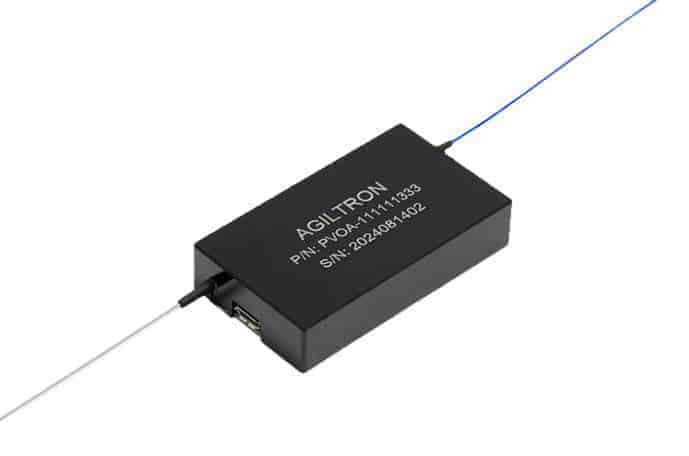 Linear Digitally Control MEMS Variable Attenuators
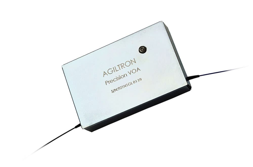 Large Core Fiber Variable Attenuator USB/RS232
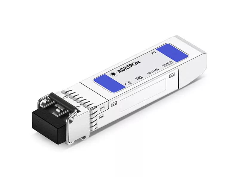 SFP Variable Optical Attenuator 12
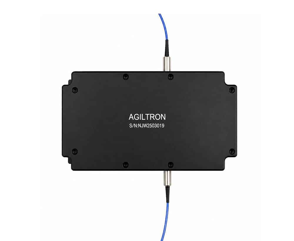 High Power Inline Variable Fiber Attenuator up to 20W USB/RS232
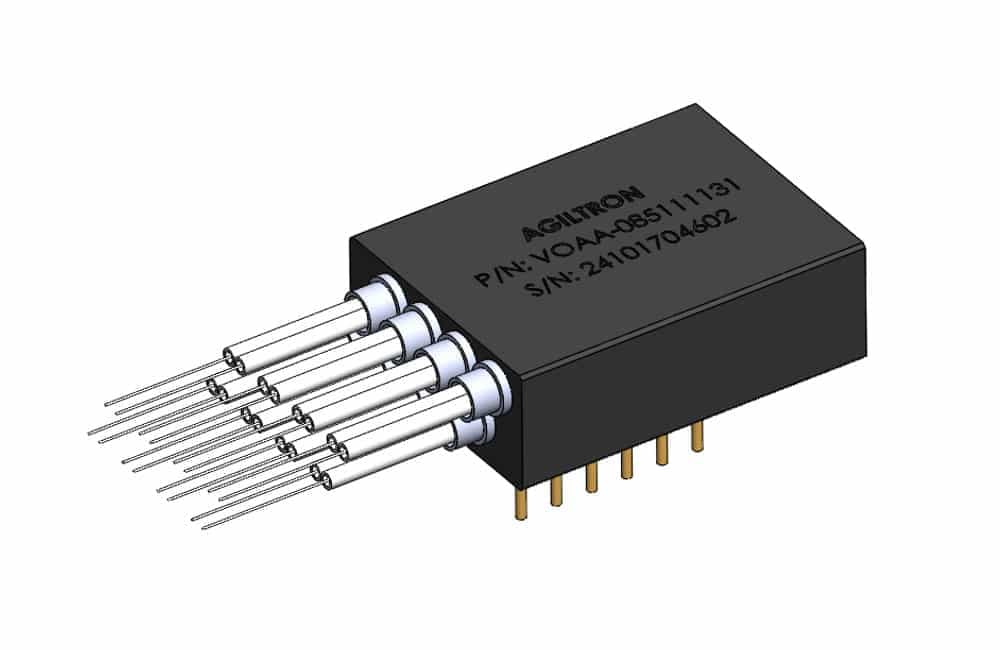 Ultra-Mini MEMS Variable Attenuation Array
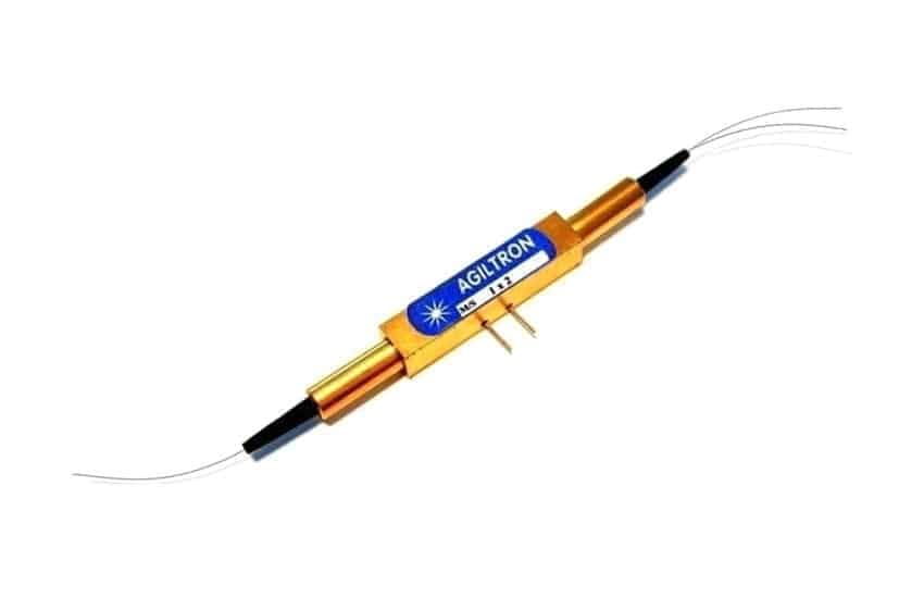 High Speed Premium Variable Fiber Optical Attenuator 350-2400nm, 18dB