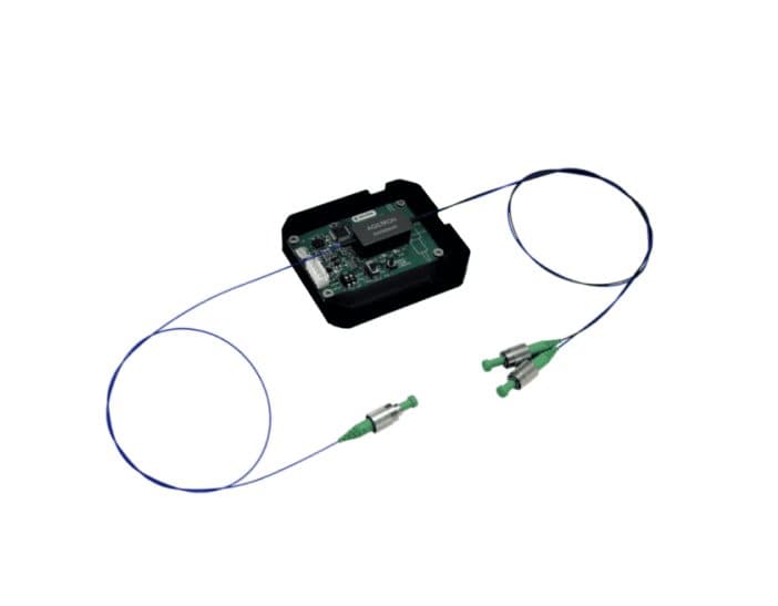
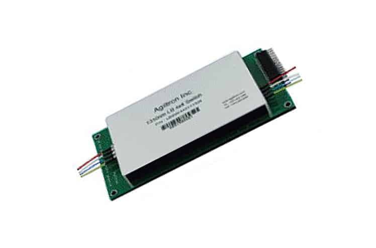
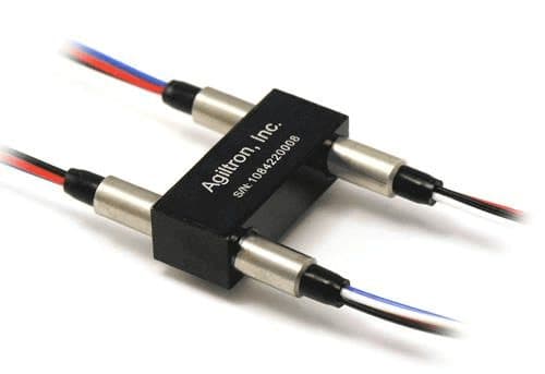
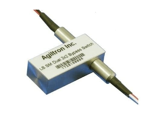
Optical Switches
Ultra-Low Latency Multicast Switch Multi-Port Output
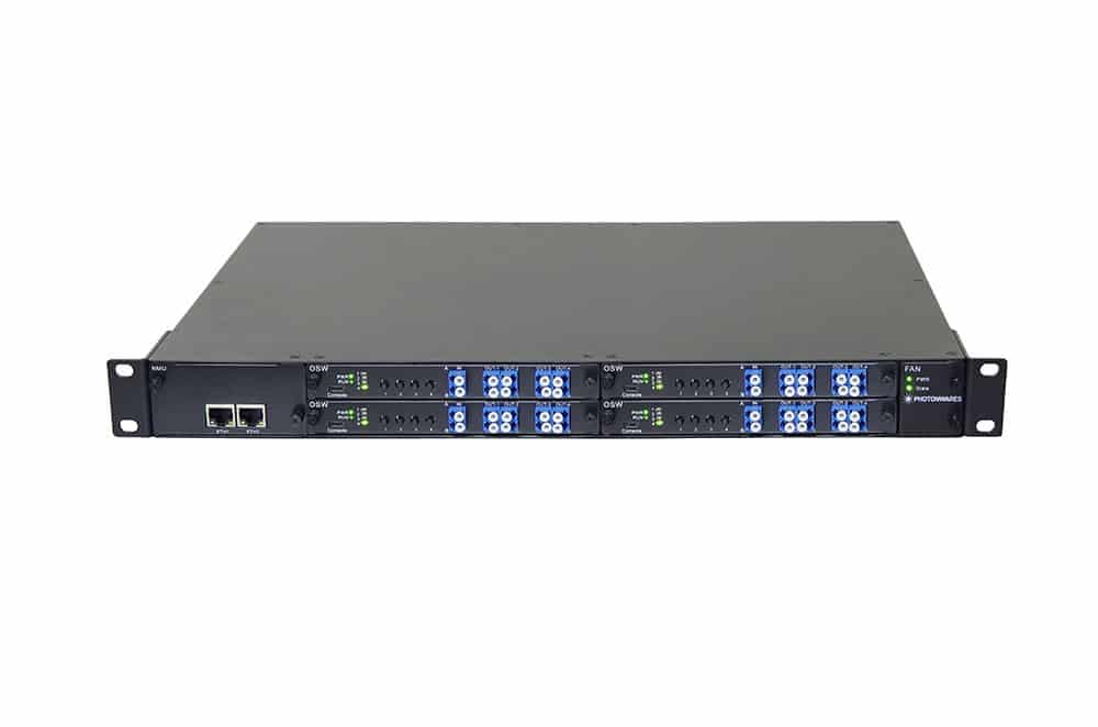
Our optical routers achieve ultra-low latency, which has not been attainable by electronic routers. The 1U system multicast incoming optical signals and dynamically re-directs them into multiple output ports with built-in optical MEMS switches and amplifiers. These switches are controlled via Ethernet-GUI or RS232-GUI. The fiber output ports are located in the front panel.
Configuration options
Build & quote
Configure the options below and add your exact build to the enquiry — we confirm the part number and availability.
We confirm the exact part number for your configuration on enquiry.
Input: 1 · Output: 12 · Wavelength: 1310 · Latency: 20ns · Package: 1U · Control: RS232 · Power Supply: 12V DC · Connector: FC/PC · Interface Code: Non
System integration
Integration and compatibility
Use these checks to connect Ultra-Low Latency Multicast Switch Multi-Port Output to the surrounding optical, mechanical and control system. Every value shown is taken from this model's own specification record.
- Optical interface and fiber
- Connector: FC/PC, FC/APC, SC/PC, SC/APC, ST/PC, LC, Duplex LC, Special · Interface Code: Non, Python, LabVIEW
- Specify connector polish and fiber architecture together. FC/PC, FC/APC and SMA interfaces, and single-mode, multimode and polarization-maintaining fibers, impose different return-loss, mode-field and alignment requirements.
- Wavelength and loss budget
- Wavelength: 1310, 1550, Special
- Check the Optical Switches passband, insertion loss, return loss and power handling at the actual source wavelength; a nominal telecom-band label is not a substitute for the configured range.
- Control interface
- Control: RS232, USB, Ethernet · Power Supply: 12V DC, 48V DC, 110~220V AC, Special
- Match supply voltage, analog or digital command range, connector pinout and default optical state to the instrument interlock. Confirm the unpowered state explicitly — it decides what happens to the link on a power failure.
Technical FAQ
Integration questions for Ultra-Low Latency Multicast Switch Multi-Port Output
Which fiber and connector does the Ultra-Low Latency Multicast Switch Multi-Port Output use?
Connector: FC/PC, FC/APC, SC/PC, SC/APC, ST/PC, LC, Duplex LC, Special · Interface Code: Non, Python, LabVIEW. Specify connector polish and fiber architecture together. FC/PC, FC/APC and SMA interfaces, and single-mode, multimode and polarization-maintaining fibers, impose different return-loss, mode-field and alignment requirements.
How should the Ultra-Low Latency Multicast Switch Multi-Port Output be included in an optical power budget?
Wavelength: 1310, 1550, Special. Check the Optical Switches passband, insertion loss, return loss and power handling at the actual source wavelength; a nominal telecom-band label is not a substitute for the configured range.
Does the Ultra-Low Latency Multicast Switch Multi-Port Output require a controller?
Control: RS232, USB, Ethernet · Power Supply: 12V DC, 48V DC, 110~220V AC, Special. Match supply voltage, analog or digital command range, connector pinout and default optical state to the instrument interlock. Confirm the unpowered state explicitly — it decides what happens to the link on a power failure.
Need this configured?
Share your wavelength, fiber type, connector, power handling and control requirements and we will qualify the matching configuration and part number.
Model selection
Nearby series comparison
Compare Ultra-Low Latency Multicast Switch Multi-Port Output with the closest available models in the Optical Switches family.
| Selection parameter | Ultra-Low Latency Multicast Switch Multi-Port Output (current) | Ultra-Fast 1×1, 1×2, 2×2 Fiber Optical Switch: 10ns, 16dB On/Off, 1MHz | Ultrafast Fiber Optical Shutter/Switch – 1ns |
|---|---|---|---|
| Wavelength range | 1310, 1550, Special | 1060nm, 2000nm, 1310nm, 1480nm, 1550nm, 1625nm, 1750nm, 780nm, 850nm, 650nm, 550nm, 450nm | 1550nm, 1310nm |
| Connector / control | FC/PC, FC/APC, SC/PC, SC/APC, ST/PC, LC, Duplex LC, Special | None, FC/PC, FC/APC, ST/PC, LC/PC, LC/APC, E2000 APC, LC/UPC | FC/APC |