Compare the details
Technical specifications
Compare the listed configurations and match the specifications to your setup.
Jump to a specification table (2)
16 specification rows.
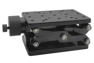
Compact platform · 120 × 80 mm
8 entries| Parameter | Specification |
|---|---|
| Platform Surface Dimensions | 120*80mm (with laser head fixing hole) |
| Lifting Stroke | 60mm |
| Minimum Height | 60mm |
| Maximum Height | 120mm |
| Load-bearing | 20KG |
| Weight | 1.15KG |
| Material | Hard Aluminum |
| Surface | Anodized Black Treatment |
Large platform · 210 × 150 mm
8 entries| Parameter | Specification |
|---|---|
| Platform Surface Dimensions | 210*150mm (with laser head fixing hole) |
| Lifting Stroke | 120mm |
| Minimum Height | 80mm |
| Maximum Height | 200mm |
| Load-bearing | 30KG |
| Weight | 3.8KG |
| Material | Hard Aluminum |
| Surface | Anodized Black Treatment |
Build around your experiment
What to specify
Share these details with your enquiry so we can match the component to your optical setup.
- 01Laser model, wavelength, operating mode and power.
- 02Mounting footprint, clearances and operating environment.
- 03Thermal load, electrical interfaces and any enclosure requirements.
Technical FAQ
Configuration questions for Lab Platform
How is the Lab Platform constructed?
Material: Hard Aluminum. Skin thickness and core construction set the stiffness that the isolation system is then asked to support. A thin-skinned top on good isolators still flexes locally under a clamped load.
What size is the Lab Platform?
Platform Surface Dimensions: 120*80mm (with laser head fixing hole) · Surface: Anodized Black Treatment. Lay the intended optical path out on the stated working area before ordering. Beam paths grow, and a table that is exactly large enough on paper is generally too small in practice.
What load does the Lab Platform support?
Load-bearing: 20KG · Weight: 1.15KG. Budget the installed mass including instruments that arrive later. Pneumatic isolators in particular have a working load band rather than a single maximum, and behave poorly below it as well as above.
Technical documents
Keep the specifications at hand when planning your setup.
Download datasheet (PDF)Talk through your setup
Find the right configuration
Add this component to your enquiry and include your requirements. We will help specify the variant, interfaces and mounting.