Laboratory optical integration
F-Theta Scanning Lens: The component is selected by matching its interfaces and error contribution to the complete instrument budget.

Laser components & accessories
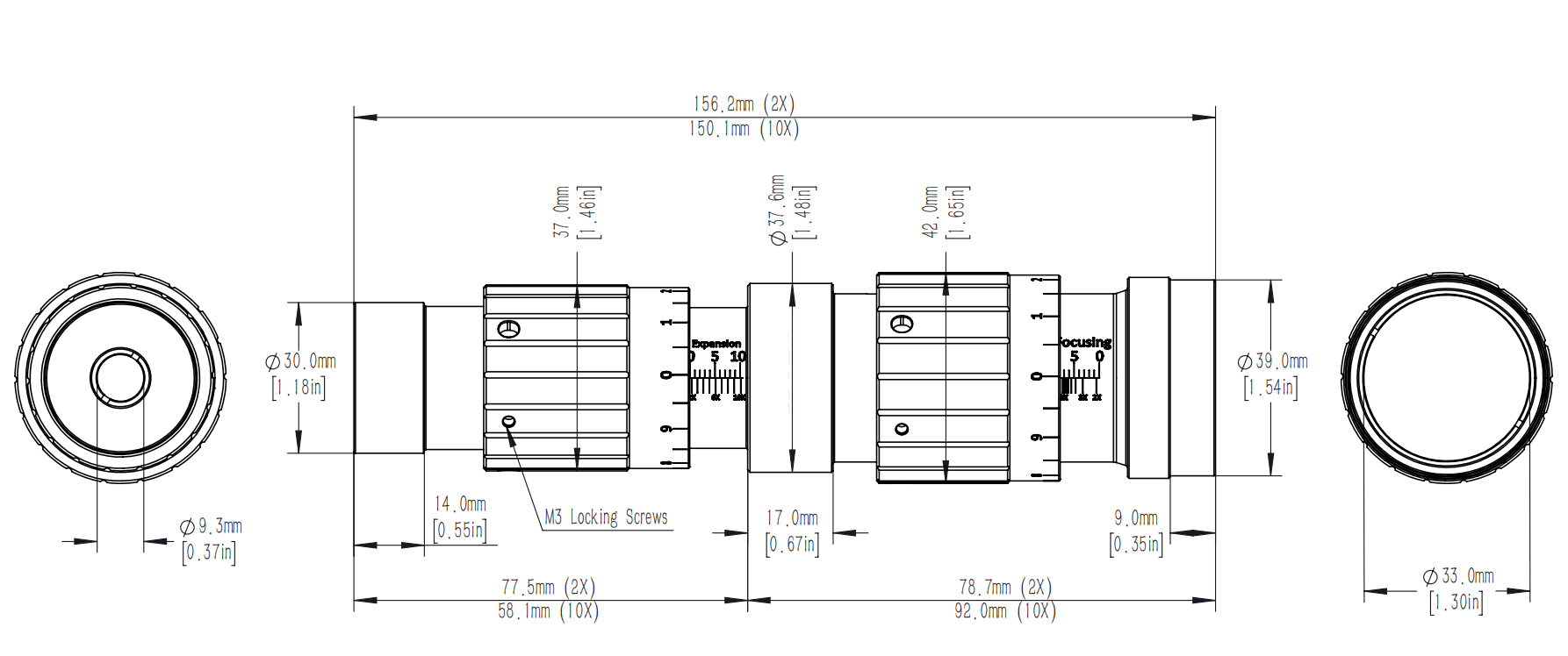
F-Theta Field Scanning Lens 1. F-theta mirrors are used in conjunction with oscillators for laser marking, welding, engraving, etc. 2. Commonly used field mirror lenses are plain optical glass, all-quartz and a mixture of both, depending on the power and pulse width of the input laser. All quartz field lenses are commonly used for high power laser and picosecond laser applications. 3. Uniform beam size over the full width, with aberrations <1%.
| Wavelengths (nm) | Effective Focal Length (mm) | Scanning Format (mm) | Entrance Pupil (mm) | Datasheet |
|---|---|---|---|---|
| 355 | 100~1117 | 50~800 | 6~18 | |
| 405 | 175 | 110*110 | 6 | |
| 532 | 120~260 | 65~170 | 10~20 | |
| 1064 | 50 | 18 | 26.7 |
Application context
Application fit depends on the ordered configuration; catalog values are separated from fields that still require confirmation.
F-Theta Scanning Lens: The component is selected by matching its interfaces and error contribution to the complete instrument budget.
F-Theta Scanning Lens: A documented configuration prevents optical, mechanical and control assumptions from becoming integration failures.
Engineering reference
F-Theta Scanning Lens is a configurable configurable scientific component in the Laser components and accessories family. The final part number should be released only after the optical, mechanical, electrical and environmental fields below are matched to the intended instrument.
This component must be qualified inside the complete optical, mechanical and electrical chain. Interfaces, performance limits and environmental conditions are coupled; a model name alone is not sufficient to release an instrument design.
Selection guidance describes the engineering fields that must be checked. It does not assign an option-dependent value that is absent from the catalog record.
Technical FAQ
Confirm primary function, operating range, performance budget, physical interface, control interface, and environment. These fields are coupled, so the final part number should be checked against the complete instrument rather than selected from the model name alone.
This component must be qualified inside the complete optical, mechanical and electrical chain. Interfaces, performance limits and environmental conditions are coupled; a model name alone is not sufficient to release an instrument design. Freeze the optical, mechanical and electrical interfaces before releasing the surrounding assembly.
Approve the configuration-specific specification, mechanical drawing, connector or pinout definition, environmental suffix and acceptance-test limits supplied with the quotation. Any field absent from the local record remains a confirmation item, not an assumed capability.