Compare the details
Technical specifications
Compare the listed configurations and match the specifications to your setup.
Jump to a specification table (4)
27 specification rows.
Fixed-ratio beam expanders
7 entriesScroll horizontally to compare all columns
| Model | Expansion ratio | Dimensions · III & F (mm) | Dimensions · FN (mm) |
|---|---|---|---|
| BE-2x | 2X | Φ25*50.5 | Φ25*50.5 |
| BE-3x | 3X | Φ42*84.8 | Φ42*87.8 |
| BE-4x | 4x | Φ42*84.8 | Φ42*87.8 |
| BE-5x | 5X | Φ42*84.8 | Φ42*87.8 |
| BE-8x | 8x | Φ56*147.8 | Φ56*150.8 |
| BE-10x | 10X | Φ56*147.8 | Φ56*150.8 |
| BE-15x | 15x | Φ56*192.8 | Φ56*195.8 |
Beam-expander stands
2 entries| Model | Dimensions (L × W × H) |
|---|---|
| BES-01 | 75 × 50 × 101 mm |
| BES-02 | 75 × 50 × 119 mm |
BEW beam expanders
4 entriesScroll horizontally to compare all columns
| Part No. | Expansion ratio | Dimensions (mm) |
|---|---|---|
| BEW-2x | 2X | Φ29*51 |
| BEW-3x | 3X | Φ42*87.8 |
| BEW-5x | 5X | Φ45*123.8 |
| BEW-10x | 10X | Φ84*209 |
Variable beam expander · 2×–10×
14 entries| Parameter | Specification |
|---|---|
| Working wavelength | 355nm/532nm/1064 nm |
| Rate of adjustment | 2X-10X |
| element material | Uv fused quartz |
| Transmittance | ≥96% |
| Surface finish | 40/20 |
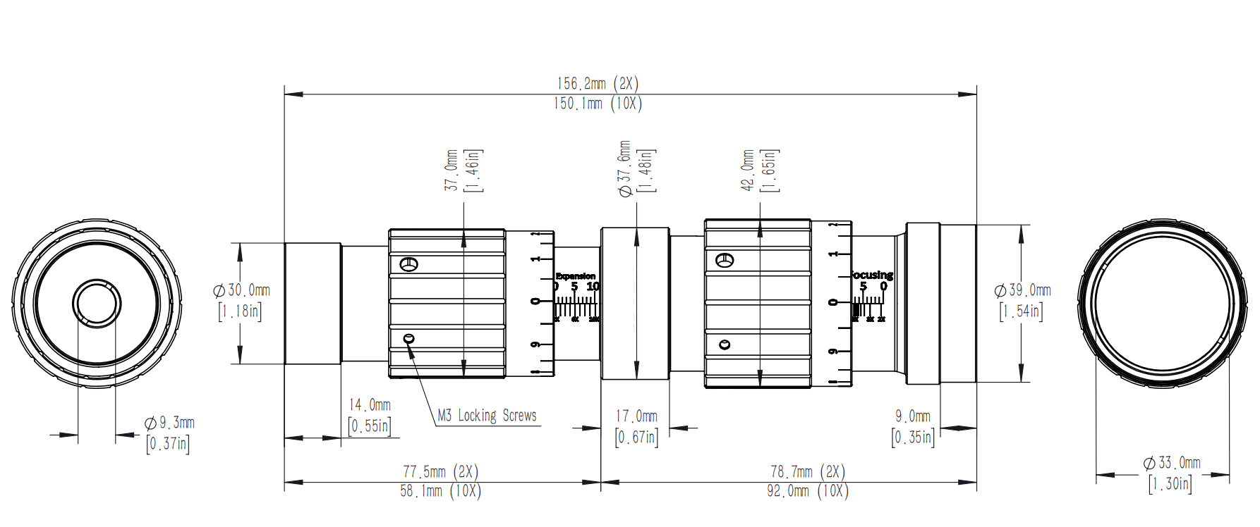
| Incident light aperture | 9.3 mm |
| Weight | ~0.25 kg |
| Outgoing light aperture | 33.0 mm |
| Locking method | M3 rubber head screw |
| Diffraction limit: The maximum diameter of the incident beam | 2.2-6.0 mm @355nm 3.0-8.0 mm @532nm 3.0-8.0 mm @1064nm |
| Length of mechanical parts (2X) | 155.1 mm @355nm 156.2 mm @532nm 158.6 mm @1064nm |
| Mechanical part length (10X) | 150.5 mm @355nm 150.1 mm @532nm 153.5 mm @1064nm |
| Membrane layer damage threshold | 2.5 J/cm²;1.0MW/cm² @355nm 5.0 J/cm²;2.5MW/cm² @532nm 10 J/cm²;5MW/cm² @1064nm |
| System damage threshold | 0.25 J/cm²;0.1MW/cm² @355nm 0.5 J/cm²;0.25MW/cm² @532nm 1.0 J/cm²;0.5MW/cm² @1064nm |
Build around your experiment
What to specify
Share these details with your enquiry so we can match the component to your optical setup.
- 01Operating wavelength, beam diameter and continuous or pulsed power.
- 02Required beam geometry, aperture, coating and polarization.
- 03Working distance, mechanical envelope and mounting interface.
Technical FAQ
Configuration questions for Beam Expander
What wavelengths does the Beam Expander cover?
Working wavelength: 355nm/532nm/1064 nm. Check the specification at your angle of incidence. Coating bands and grating efficiency curves are quoted at a reference angle, and both shift as that angle changes.
What size is the Beam Expander?
Incident light aperture: 9.3 mm · Outgoing light aperture: 33.0 mm. Clear aperture is smaller than the physical part, and the mount that holds it takes more again. Size the optic from the beam diameter at that plane, including the margin the mount consumes.
How much optical power can the Beam Expander take?
Membrane layer damage threshold: 2.5 J/cm²;1.0MW/cm² @355nm 5.0 J/cm²;2.5MW/cm² @532nm 10 J/cm²;5MW/cm² @1064nm · System damage threshold: 0.25 J/cm²;0.1MW/cm² @355nm 0.5 J/cm²;0.25MW/cm² @532nm 1.0 J/cm²;0.5MW/cm² @1064nm. Damage thresholds are quoted for a pulse duration, wavelength and beam diameter. Scale them to your own conditions rather than reading the headline figure as a rating.
What is the Beam Expander made from?
element material: Uv fused quartz · Surface finish: 40/20. Substrate and coating decide thermal behaviour and cleaning method as much as optical performance. Confirm both before the optic enters a high-average-power or vacuum path.
Technical documents
Keep the specifications at hand when planning your setup.
Download datasheet (PDF)Talk through your setup
Find the right configuration
Add this component to your enquiry and include your requirements. We will help specify the variant, interfaces and mounting.