01 · UV curing: what actually hardens the resin?
A photon starts a chain reaction. Everything else is bookkeeping.
A UV-curable resin is a liquid of reactive monomers and oligomers, usually acrylates or methacrylates, sometimes epoxides or vinyl ethers, with a small amount of a photoinitiator. The photoinitiator is the only component that has to absorb the light. When it does, it breaks apart or abstracts a hydrogen from a neighbour and produces a radical (or, in cationic systems, an acid). That radical attacks a carbon–carbon double bond, which becomes a new radical, which attacks the next one, and within seconds a liquid of small molecules has become a cross-linked solid. One absorbed photon can convert thousands of double bonds; the light is a trigger, not the energy that builds the network.
This is not drying. A solvent-borne coating hardens when the solvent leaves and the film that remains was already a polymer. A UV resin is typically 100 % solids: nothing evaporates, the mass that goes on stays on, and hardness comes from chemical bonds formed during exposure. That is why a UV cure can happen in seconds inside a closed joint, and also why it cannot happen at all where the light does not reach.
Four things must line up, and a failure of any one of them looks the same from the outside. The source wavelength must fall where the initiator absorbs. The irradiance at the resin sets how fast radicals are produced, which decides whether the surface layer cures faster than oxygen can stop it. The exposure — irradiance integrated over time — sets how far the conversion proceeds. And the formulation decides how deep the light gets: the same initiator that makes the surface cure quickly also absorbs the light before it reaches the bottom.
Fixation
The gel point: enough network has formed that the part holds position and can be handled or moved to the next station. Adhesive datasheets call this fixture time. It is reached in seconds and proves nothing about strength or depth.
Surface cure
The exposed face stops being tacky. For radical acrylates this is the last part to cure, because oxygen from the air scavenges radicals at the surface; a tack-free face therefore says the surface has beaten oxygen inhibition, not that the bulk is converted.
Through-cure
Conversion at the bottom of the layer or the far side of the bond line, where irradiance is lowest. Set by absorption through the depth and by the dose at the surface, and the part of the cure that cannot be inspected by looking at it.
Final properties
Modulus, glass-transition temperature, adhesion and chemical resistance keep developing after exposure: dark cure in cationic systems, post-cure conversion, and adhesion build over hours to days. NOA 61, for example, reaches optimum adhesion to glass after about a week at room temperature or 12 h at 50 °C.
These four are reached at different exposures and are verified by different tests. A process that only checks the first two will ship joints that fail later.
02 · Compare UV LEDs, lasers and broadband lamps
Three ways to make the same photon arrive.
A photoinitiator does not care where its photon came from. What differs between sources is the spectrum around that photon, the area it is spread over, how precisely it is placed, and what else arrives with it — heat, short-wave UV, or a Class 4 hazard.
| UV LED (spot, multi-head, flood) | UV laser (355 nm DPSS, 375/405 nm diode) | Broadband lamp (Hg, doped Hg, microwave) | |
|---|---|---|---|
| Spectral output | Narrow band, typically ±10–15 nm around 365, 385, 395 or 405 nm; deep-UV heads at 255–280 nm exist at much lower output. No UV-B/UV-C unless ordered; little infrared. | Single line: 355 nm from a Q-switched DPSS source, 375 or 405 nm from a laser diode. Nothing outside the line, so the photoinitiator must absorb exactly there. | Lines at 254, 313, 365, 405, 436 nm plus a continuum, shifted by dopants (Fe, Ga) toward 350–420 nm. Broad overlap with almost any initiator, plus IR heat and, for short-arc types, ozone. |
| Material compatibility | Works when the datasheet names the LED wavelength. Modern acrylates and most cationic epoxies formulated for 365 nm cure well; older lamp-formulated resins may need a Type II initiator band the LED does not cover. | Excellent for materials specified for 355 nm (lithography resists, laser-cure adhesives); many general-purpose adhesives will also respond, but absorption is strong and penetration shallow. Confirm per resin. | Cures the widest range of legacy formulations because something in the spectrum reaches every initiator. Also drives photodegradation and heating that the resin was never meant to see. |
| Spot versus area | Spot heads of Ø4–50 mm; several heads on one controller for multi-point work; flood heads for 10×10 to 35×35 mm. Larger areas by arrays or stepping. | Sub-millimetre to few-millimetre spots. Areas only by scanning, patterning or beam expansion, which trades irradiance for coverage. | Flood and conveyor illumination over hundreds of millimetres. Poor at small spots without a lightguide, which discards most of the output. |
| Spatial selectivity and uniformity | Collimating and focusing optics give a defined spot with usable uniformity; irradiance falls steeply away from focus. Selectivity is the spot size. | The highest selectivity available: cure a dot, a line or a pattern and leave the rest liquid. Gaussian profile, so uniformity comes from scan overlap or beam shaping, not from the source. | Uniform over large areas at the reflector focus; edges roll off. No selectivity without masks. |
| Optical delivery and working distance | Direct head, typically 20–150 mm working distance, or a liquid lightguide. Simple fixturing on a holder. | Free-space beam through a scanner and f-theta lens, or a fibre-coupled variant. Working distance set by the focusing lens; alignment and beam path are yours to engineer. | Reflector focus a fixed distance below the housing, or a lightguide from a spot lamp. Bulky and hot near the part. |
| Timing and intensity control | Instant on/off, 10–99 % power, timers from seconds to hours, foot switch, USB control. Repeatable shot-to-shot. | Pulse-level control: energy, repetition rate and external trigger. Exposure is programmed as a scan path and a pulse train. | Warm-up of minutes, shutter timing, limited dimming, and output that declines over bulb life; needs frequent radiometer checks. |
| Thermal management and maintenance | Fan-cooled head; little radiant heat on the part. Rated lifetimes above 25 000 h with no consumables. | Air-cooled head with warm-up of minutes; heat on the part is local to the spot and scales with average power. Lifetimes above 10 000 h; no lamps to change. | Strong IR heating of the part; bulbs replaced every few hundred to few thousand hours; reflectors and filters degrade; ozone extraction for short-wavelength types. |
| Integration complexity | Lowest: a head, a driver, a holder and a radiometer. Standard eye and skin protection for UV-A or violet light. | Highest: Class 3B/4 laser safety with enclosure and interlocks, beam delivery, scanner and software, plus a power meter at the work plane. | Moderate: power, cooling, shielding and bulb handling; safety for UV-B/UV-C and ozone if the spectrum reaches there. |
| Typical applications | Optical assembly, lens and fibre bonding, electronics tacking and conformal coatings, medical device assembly, lab curing of small parts. | Selective curing in fixtures where light must not reach neighbouring parts, patterned exposure, micro-assembly, photolithography-type work, research on cure kinetics. | Large-area coatings, printing and converting lines, legacy processes qualified on a specific bulb. |
Choose an LED when
the job is a joint, a dot, a fibre, a lens or a coating patch of a few millimetres to a few centimetres, the resin names 365, 385, 395 or 405 nm, and you want a recipe that repeats without a bulb ageing underneath it. This is most optical-assembly and electronics work, and it is where our UV LED curing systems sit.
Choose a laser when
light must land on one region and nowhere else, when the pattern is the product, when the material is specified for 355 nm, or when exposure has to be synchronised pulse by pulse with motion. Accept beam delivery, a scanner and a Class 3B/4 safety envelope as part of the price.
A broadband lamp fits when
a legacy formulation was qualified on a specific bulb spectrum, or a wide conveyor needs metres of uniform flood. We do not offer lamp curing systems; the comparison is here so that you can judge an LED or laser replacement honestly, spectrum first.
03 · Choose the wavelength for the material
The datasheet names the band. Everything in the light path has to pass it.
Three spectra decide a cure: the source emission, the initiator absorption, and the transmission of whatever sits between them — a cover glass, a plastic housing, the substrate if you cure from below, or the resin itself once pigments and fillers are in it. The cure happens only where all three overlap. A resin datasheet expresses this as a wavelength or a band: NOA 61, for instance, absorbs most strongly at 350–380 nm and asks for 3 J/cm² there; Loctite 3972 states its fixture and cure figures at irradiances “measured at 365 nm”. Start from that statement, not from the source you happen to own.
Shorter is not deeper. Absorption by most initiators rises steeply toward the UV, so a 355 nm beam is absorbed in a thinner layer than 365 nm, and 385 or 395 nm goes deeper still — if the initiator absorbs there at all. Deep-UV heads at 255–280 nm are absorbed within micrometres and deliver a fraction of the output of a 365 nm head. Shorter wavelength buys surface cure and pattern sharpness; it does not buy through-cure. The manufacturer of our LED heads recommends 365 nm as the general-purpose choice for exactly this reason: nearly every formulation responds there, whereas 405 nm needs a formulation built for it.
405 nm is violet visible light, not ultraviolet. Its value is that it passes through most UV-blocking plastics and cures initiators such as the acylphosphine oxides that absorb past 400 nm, which is why 3D-printing resins and many low-migration adhesives are formulated for it. Its cost is that a resin specified for 365 nm may barely respond, and that eyewear rated for UV alone may transmit it.
Covers and substrates. Polycarbonate absorbs strongly below roughly 385–400 nm; acrylic (PMMA) usually transmits UV-A unless it is a UV-stabilised grade; soda-lime glass passes 365 nm but not 300 nm; polyester film cuts off near 320 nm. The manufacturer of our heads notes that a “transparent” plastic can block 365 nm entirely, which is why the 405 nm head exists. Measure the transmission of the actual part at the actual wavelength; visible clarity tells you nothing about 365 nm.
| Wavelength | Source type | What it does in the resin | Where it fits |
|---|---|---|---|
| 355 nm | DPSS laser line, UV-A | Strongly absorbed by most initiators and by many glasses and plastics; shallow penetration, sharp patterns. | Patterned or localised curing, thin layers, materials specified for 355 nm. |
| 365 nm | LED and mercury i-line, UV-A | The reference band for most adhesive and coating formulations; Type I and Type II initiators absorb here. | Default choice when the resin datasheet says 365 nm or gives a 320–380 nm band. |
| 385 / 395 nm | LED, UV-A | Higher LED efficiency and deeper penetration through mildly absorbing or thicker layers; needs initiators with absorption tails past 380 nm (TPO, BAPO types). | Thick clear layers, some pigmented systems, resins formulated for “LED 395”. |
| 405 nm | LED or laser diode; violet visible light | Not ultraviolet. Passes covers that block UV, cures only initiators with strong absorption above 400 nm; lower-energy photons, so the formulation must be built for it. | Curing through UV-blocking plastics, 3D-printing and dental-type resins, low-migration systems. |
| 255–280 nm | Deep-UV LED, UV-C | Very low LED output, absorbed within micrometres, strong skin and eye hazard, ozone below 240 nm. | Surface-only processes and disinfection-type work, not bulk curing. |
04 · Understand power, irradiance and dose
Four quantities that share a unit prefix and nothing else.
W
Electrical input power
What the head or lamp draws from the supply. A 14 W LED head and a 150 W flood head say nothing about light on the part; efficiency and optics sit in between.
W
Optical output power
Radiant power leaving the source. Quoted for lasers (an average, for pulsed sources) and for LED chips; rarely the figure you need, because it is spread over an area you have not chosen yet.
mW/cm² or W/cm²
Irradiance at the workpiece
Optical power per unit area at the resin. The number a radiometer reads, the number resin datasheets quote, and the number that decides whether the surface beats oxygen inhibition.
mJ/cm² or J/cm²
Radiant exposure (“dose”)
Irradiance integrated over time. The number that decides how far conversion proceeds, provided the wavelength and the irradiance regime are the ones the datasheet assumed.
Radiant exposure is the time integral of irradiance, H = ∫ E(t) dt. With a source that switches on to a constant level and off again, which is what an LED head with a timer does, this collapses to H = E × t: a 100 mW/cm² source delivers 100 mJ/cm² per second, 1 J/cm² in ten seconds. A lamp warming up, a pulsed laser, or a scanned beam are not constant, and the integral has to be done properly — or measured with a dosimeter that does it for you.
Worked example: NOA 61 under a 365 nm LED spot head
- Material requirement. The NOA 61 datasheet states maximum absorption at 350–380 nm and recommends 3 J/cm² for full cure in that band.
- Source. A SUVA 365 nm head set to a Ø25 mm spot is rated 100–150 mW/cm² by its manufacturer at that spot size.
- Measurement. A UV-A radiometer at the bond plane, same distance and same power setting as production, reads 120 mW/cm². (Assumption: the radiometer band covers 365 nm and nothing sits between head and resin.)
- Exposure. t = 3 000 mJ/cm² ÷ 120 mW/cm² = 25 s for the recommended dose. At the Ø4 mm focus, rated 2.5–5.5 W/cm², the same dose arrives in about 1 s — over a spot that no longer covers the joint.
- Process. The datasheet suggests a short precure to fix alignment, then the full cure; and optimum adhesion to glass only after about a week of ageing. The 25 s is an exposure, not a proof of properties.
Equal dose is not equal cure. Reciprocity — the idea that halving the irradiance and doubling the time gives the same result — holds only over a limited range. At low irradiance, oxygen diffusing into the surface consumes radicals as fast as they are made, so the surface stays tacky at any dose. At very high irradiance, radicals are made faster than they can find monomer and terminate each other, so conversion per photon falls; in a model methacrylate resin, conversion at a fixed dose was measured to change with intensity, and the dose needed for full conversion rose with intensity. A different spectrum changes which initiator molecules absorb and how deep; a warmer resin cures faster and further because chain mobility is higher. The datasheet dose is a starting point at the datasheet's irradiance, wavelength and temperature.
The Loctite 3972 datasheet shows the same point from the other side: fixture on glass in ≤ 7 s at 6 mW/cm² and in < 5 s at 100 mW/cm², but the cured-material properties it publishes are for 30 s at 100 mW/cm² per side — 3 J/cm², some four hundred times the exposure that produced fixture. Fixture time and full cure are different quantities answered by different tests.
Exposure estimator
Dose and exposure time
Enter the irradiance you measured at the actual cure plane and the radiant exposure your resin datasheet asks for. The calculator applies H = E × t and nothing else.
From a radiometer whose spectral band covers your source, placed where the resin will be, at the working distance and power setting you will use.
There is no universal figure for “UV resin”. Use the value your material supplier states for its own wavelength band and cure criterion.
Leave at 100 % if you measured through the cover already. Otherwise use the transmission at the source wavelength, not the visible transparency.
Optional allowance for source ageing, positioning scatter and radiometer tolerance. 1.0 means the datasheet figure exactly.
Exposure estimate
25.0 s
t = (3,000 mJ/cm² × 1) ÷ 120.0 mW/cm²
- Effective irradiance
- 120.0 mW/cm²
- Dose in 30 s
- 3.60 J/cm²
This is an exposure estimate, not a prediction of complete cure.
- Assumes constant irradiance for the whole exposure (H = E × t) and a radiometer that reads the same band the resin responds to.
- Assumes the datasheet dose applies at your wavelength, layer thickness and temperature. Equal dose at a different irradiance can give a different conversion.
- Irradiance measured at the surface says nothing about what reaches the bottom of a thick or pigmented layer.
- Confirm with a cure test on the real joint: hardness, solvent rub, FTIR conversion or bond strength, not surface tack alone.
05 · Match the illumination to the job
Irradiance is power divided by an area you choose.
Spot size and working distance. A focusing head concentrates its output in a small spot at one distance and spreads it beyond. The SUVA head is the plain illustration: Ø4 mm at focus gives 2.5–5.5 W/cm²; opened to Ø25 mm the same light gives 100–150 mW/cm², a factor of about forty, which is the ratio of the areas. Choosing a spot that just covers the joint is the cheapest way to raise irradiance; moving the head is the easiest way to lose it, which is why the head goes in a holder and the distance goes in the recipe.
Beam profile and uniformity. A lensed LED head is designed for a reasonably flat spot; a laser beam is Gaussian and delivers several times more at its centre than at its edge. Any area larger than one spot is built from overlapping spots, and the process must be written for the dimmest point of the overlap — usually an edge or a corner. Measure the map; do not assume it.
Access and shadows. Light travels in straight lines; resin does not. A fillet under a lens edge, a bond line between opaque parts, or the far side of a three-dimensional part sees only what is scattered or transmitted to it. Shadowed volume needs a second illumination direction, a transmissive substrate, or a dual-cure (UV plus heat or moisture) formulation. Multi-head systems exist for this reason: four SUVC heads can surround a part and fire together.
Surface irradiance versus depth. What the radiometer reads is the top of the layer. Inside it the light falls off exponentially with the absorption coefficient of the resin, and the cured depth grows only with the logarithm of the surface dose — the stereolithography working curve, Cd = Dp·ln(E/Ec). Doubling the dose adds a fixed increment of depth; ten times the dose adds about three of them. Pigment or filler shortens Dp and no amount of time recovers it.
Pulsed lasers: average power, pulse energy and peak intensity
A Q-switched laser delivers its energy in nanosecond bursts. Three numbers describe it and they are not interchangeable: pulse energy (µJ), repetition rate (kHz) and their product, average power (mW), which is what a thermal power meter reads and what the dose calculation uses. Peak power is pulse energy divided by pulse duration; divided again by the spot area it becomes a peak intensity that can reach MW/cm² to GW/cm² at a tight focus — enough to ablate, bleach the initiator or damage the substrate long before the resin has received a curing dose.
Take the MPL-F-355 at 15 µJ and 4 kHz: 60 mW average, and with ~6 ns pulses a peak power of about 2.5 kW. Focused to a Ø50 µm spot, each pulse alone delivers roughly 0.76 J/cm² — a full curing dose in one shot — at a peak intensity above 10⁸ W/cm². Expanded to Ø2 mm, the same laser gives about 1.9 W/cm² average irradiance and 0.5 mJ/cm² per pulse; a 3 J/cm² dose then takes about 1.6 s per spot at a peak intensity near 80 kW/cm². The laser has not changed; the optics have decided whether it cures or cuts.
Scan overlap. Moving a spot at speed v with repetition rate f places pulses v/f apart. At 4 kHz and 100 mm/s that is 25 µm, half a Ø50 µm spot, so each point receives two pulses per line; line pitch sets the overlap in the other axis. Dose per unit area is then pulse fluence times pulses per point, and uniformity is a property of the scan, not of the beam.
Average power
P = E_pulse × f_rep
15 µJ × 4 kHz = 60 mW
Peak power
P_peak ≈ E_pulse / τ
15 µJ / 6 ns ≈ 2.5 kW
Fluence per pulse
F = E_pulse / A_spot
Ø50 µm: 0.76 J/cm² · Ø2 mm: 0.48 mJ/cm²
Peak intensity
I_peak = P_peak / A_spot
Ø50 µm: ~1.3×10⁸ W/cm² · Ø2 mm: ~8×10⁴ W/cm²
Average irradiance
E = P / A_spot
Ø2 mm: ~1.9 W/cm²
Pulse spacing
s = v / f_rep
100 mm/s ÷ 4 kHz = 25 µm
Figures use the MPL-F series datasheet values (0.1–15 µJ, ~6 ns, 1–4 kHz triggered); spot sizes are assumptions for illustration. Peak-intensity limits for a given resin and substrate must be established by test.
06 · Diagnose incomplete or inconsistent curing
Tack-free is where the diagnosis starts, not where it ends.
Every symptom below has more than one cause, and the causes call for different fixes. Doubling the exposure time is the usual first reaction and it addresses only one of them. No exposure time or cure depth in this section is universal; each is a direction to test in.
Tacky surface, hard underneath
- Oxygen inhibition of a radical acrylate at the air interface
- Irradiance too low for the surface layer to out-run oxygen, even if the total dose is met
- Photoinitiator band missed by a narrow LED
Direction: Raise irradiance rather than time, exclude air with a cover film or nitrogen, use a formulation with an amine synergist or a cationic system, or match the wavelength to the datasheet.
Cured skin, liquid below
- Absorption through the depth: pigments, fillers, high initiator loading or a UV-absorbing substrate
- Dose at the bottom of the layer below the gel threshold
- Wavelength too strongly absorbed (355 nm in a thick layer)
Direction: Thinner layers, a longer wavelength the resin still responds to, lower initiator concentration, exposure from both sides, or a dual-cure system for the shadowed volume.
Distortion, warping, cracked optics
- Polymerisation shrinkage stress from curing too fast or unevenly
- Thermal expansion from source heat or the exothermic reaction
- Fixing one side of a part before the other
Direction: Stage the cure: a low-irradiance fixation exposure, then full cure; illuminate symmetrically; manage part temperature; choose a lower-shrinkage material.
Yellowing or discolouration
- Over-exposure or short-wavelength content that the resin does not need
- Photoproducts of Type II initiators and amine synergists
- Heating during cure
Direction: Cure to the specified dose, not beyond; prefer a narrow LED band over a broadband lamp; choose a non-yellowing initiator package if optics are in the path.
Inconsistent bond strength part to part
- Working distance or angle varying between parts
- Source output drifting with temperature, ageing or a dirty window
- Substrate transmission varying (different plastic lots, coatings, contamination)
- Radiometer not matched to the source or not at the cure plane
Direction: Fix the head in a holder, measure at the cure plane with a radiometer whose band matches the source, log irradiance per shift, and qualify substrate lots.
How to know the cure is complete
A tack-free surface establishes surface cure only. Through-cure and final properties need a test that reaches the bulk: hardness at the bottom of a cast layer, a solvent rub or extractables test, FTIR conversion of the C=C band on a section, lap-shear or pull-off strength after the ageing time the datasheet specifies, and a glass-transition measurement if the part sees heat. Choose one test that represents the failure you care about, run it across the range of irradiance, distance and substrate you expect in production, and write the recipe from the worst case.
07 · Connect requirements to Precisometer products
From the job to a part number, with the conditions attached.
Every output figure below is quoted with the spot size and distance the manufacturer measured it at, because an irradiance without those two numbers is not a specification. The last column is what we cannot know from here and will ask you before recommending anything.
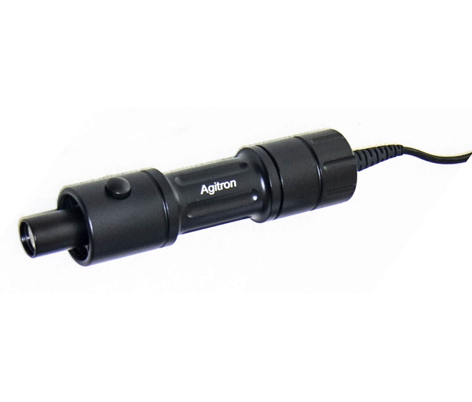
UV LED spot light, 1 head
365 nm as standard; 405 nm and other heads; Ø4–50 mm spot; timer and power control on the driver.
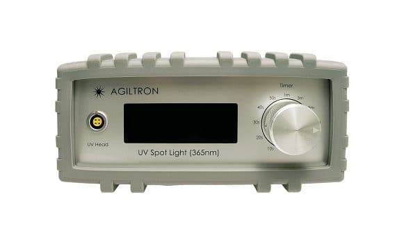
UV LED system, 4 heads, USB
Four independently switched heads, a shared timer and power setting, Windows GUI and a documented protocol.
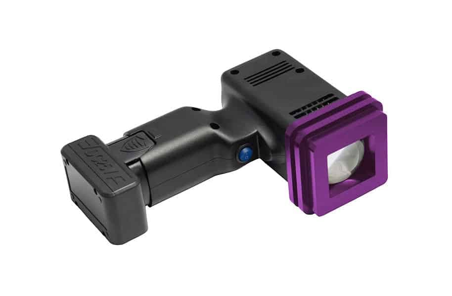
Handheld UV flood light
365, 405 or 440 nm; 10 × 10 mm to 35 × 35 mm patches; six hours per battery; optional timed controller.
| Application | Source / product | Wavelengths | Documented output (with conditions) | Illumination geometry and controls | Accessories | Confirm before ordering |
|---|---|---|---|---|---|---|
| Spot curing of adhesive dots, lens and fibre bonding, single joints | UV LED curing spot light, 1 head (SUVA) | 365 ±5 nm standard; 405 nm; 385 nm and 232–280 nm heads on request | 2.5–5.5 W/cm² at the Ø4 mm focus; 100–150 mW/cm² at a Ø25 mm spot (heads ≥ 365 nm, manufacturer datasheet). Deep-UV heads: about 0.1 W/cm² at 255 nm, 0.5 W/cm² at 280 nm. | Spot Ø4–50 mm by defocus, working distance 20–150 mm; timer 10 s–10 h; 10–99 % power; finger button or foot switch; optional USB/GUI controller | head holder, spot radiometer, goggles and head shield, foot switch, power-calibration option | Irradiance at your working distance and setting (order the calibration option or measure); availability and output of 385 nm and deep-UV heads; deep-UV control boxes are wavelength-specific. |
| Multi-point fixtures: several joints per part, semi-automated stations | UV LED curing system, 4 heads, USB (SUVC) | 365 ±5 nm, 405 nm, 440 nm (385 nm in the ordering table) | Same head class: 2.5–5.5 W/cm² at Ø4 mm, 100–150 mW/cm² at Ø25 mm (≥ 365 nm, manufacturer datasheet) | Four heads Ø22 × 110 mm on 1.5 m cables; each head switched individually from the panel, USB or a common foot switch; shared timer 10 s–18 h and power setting; Windows GUI and documented control protocol | head holders, foot switch, radiometer | Mixed wavelengths per head, cable length, PLC integration via the protocol, and whether one shared power/timer setting suits all joints. |
| Handheld and larger-area curing, repair, field work, 10–35 mm patches | Handheld UV flood light (UVFL) | 365, 405, 440 nm (±5 nm); 265 and 385 nm on request | 1.5–1.7 W/cm² at 5 mm over 10 × 10 mm; 0.9–1.1 W/cm² at 15 mm over 35 × 35 mm (≥ 365 nm, manufacturer datasheet) | Battery, 6 h per charge; spot 10–50 mm at 5–30 mm working distance; optional mains controller with timer and 10–99 % power; collimating lens option | second battery, stand, controller; black-filter variant for fluorescence inspection | Uniformity over your patch, repeatability of a handheld distance, and whether the controller is needed for a timed process. |
| Measuring irradiance at the cure plane | UV light intensity meter / spot radiometer | Sized to the LED heads | Reads the power density the head delivers at the sensor position | Place at the cure plane, same distance and power setting as the process | — | Spectral band of the detector against your head wavelength (a UV-A detector under-reads 405 nm), calibration interval, and that the same unit is used for every process check. |
| Localised or patterned curing, micro-assembly, materials specified for 355 nm | MPL-F-355 pulsed DPSS laser | 355 ±1 nm | 1–100 mW average; 0.1–15 µJ per pulse; ~6 ns pulses; 1–4 kHz internal or external trigger, 5–7 kHz free-running; TEM00, M² < 2, Ø ~1.2 mm beam (manufacturer datasheet, which lists UV curing among its applications) | Free-space beam; you supply expander, scanner or focusing optics, work-plane power meter, enclosure and interlocks | power supply included; beam delivery from our opto-mechanics range | That your resin responds at 355 nm at your layer thickness; peak intensity at the focus against ablation and substrate damage; laser class and enclosure; scan strategy for dose uniformity. |
| Faster localised curing, higher repetition rate | MPL-Q-355 pulsed DPSS laser | 355 nm | 1–150 mW average; 0.1–15 µJ; ~1.3 ns; 3–12 kHz (catalogue sheet, which lists UV curing) | As above | as above | As above; shorter pulses raise peak intensity for the same energy. |
| Higher-throughput 355 nm exposure (to be qualified) | MPL-FL-355 | 355 ±1 nm | 1–1000 mW average; 1–50 µJ; ~5 ns; ~20 kHz free-running or 1–15 kHz external trigger; Ø ~3 mm beam | As above | as above | Its datasheet lists marking, engraving and research, not curing; treat it as a throughput option that must be qualified on your resin. |
| Fibre-coupled 355 nm delivery | MPL-355 (FC) | 355 nm | The catalogue power figure and the datasheet the model is documented against do not agree; we quote neither here | Fibre-coupled | — | Full specification with us before any selection. |
| 405 nm-initiated resins with a laser (to be qualified) | MDL-III-405 (1–1000 mW) and MDL-H-405 (1–3 W) CW diode lasers | 405 nm, violet visible | Continuous 1–1000 mW or 1–3 W per the catalogue sheets | Free-space; scanning or beam expansion needed for area | as above | Their datasheets list imaging and cytometry, not curing. Suitable in principle for 405 nm-formulated resins; qualification is on you and us together. |
The LED manufacturer's 4-head datasheet names Loctite 3972, EPO-TEK OG603 and OG198, and Fiber Optic Center AB9047 and DSM956-105 as recommended adhesives. Treat that as a starting list, not a qualification of your material: the irradiance at your joint and the dose your datasheet asks for still have to be established by measurement.
We do not offer mercury or microwave lamp curing systems; the high power UV lights family lists a spare quartz UV bulb as an accessory only. Lamp comparisons in this guide are there to help you judge an LED or laser replacement against a legacy process.
08 · Three example setups
The same reasoning, three geometries.
Each example is conceptual: the products are listed and their published figures used, but the fixture, distances and exposure are illustrations, and the validation steps are what would turn them into a qualified process.
A precision adhesive joint: lens into a mount
Requirement. A Ø6 mm lens bonded into an aluminium cell with an optical adhesive specified at 350–380 nm and 3 J/cm²; the lens must be held in alignment while it fixes, and the finished joint must not yellow.
Why an LED. The joint is a few millimetres across, the resin names 365 nm, and the process needs a repeatable, timed exposure with no heat on the optic. A laser would add a scanner and a safety envelope for no gain; a lamp would add heat and short-wave UV the adhesive does not need.
Products. SUVA 1-head with a 365 nm head, head holder, spot radiometer, foot switch, goggles and head shield.
Integration. Mount the head in the holder so the Ø4–8 mm spot covers the fillet at 20–40 mm working distance; route the foot switch to the operator; fit the shield so the spot is not in the line of sight. Set the timer for the precure first, then the full cure.
Validation. Measure irradiance at the fillet plane at the production power setting; compute the exposure for the datasheet dose; confirm fixture by a gentle push test after the precure; confirm full cure by lap-shear on coupons after the datasheet's ageing time; log irradiance at the start of every shift with the same radiometer.
A resin layer or coating over a 60 × 60 mm plate
Requirement. A 0.2 mm clear acrylate coating over a 60 × 60 mm glass plate, cured in one station to a tack-free, solvent-resistant finish at a few parts per minute.
Why multi-head LED. The area is too large for one spot at useful irradiance and too small for a conveyor lamp. Four heads opened to about Ø25–30 mm each and overlapped cover the plate; the 100–150 mW/cm² per head at that spot size is in the range coating datasheets typically quote, and a shared timer fires them together. For a thicker or pigmented layer the same station would move to 395 or 405 nm heads if the resin allows it.
Products. SUVC 4-head system with 365 nm heads, four holders, foot switch, radiometer. For hand-finishing or rework, the handheld flood light covers 35 × 35 mm at 0.9–1.1 W/cm².
Integration. Mount the heads on a rail at equal height; set defocus so adjacent spots overlap by roughly a third; enclose the station with a UV-blocking screen; connect the USB GUI or protocol if the line controller sets the timer.
Validation. Map irradiance across the plate at centre, edges and corners; write the exposure for the minimum; run a cast-layer hardness test at the dimmest point and a solvent-rub test across the plate; check for edge tack and for warping of the plate from uneven cure; repeat the map after any head is moved or replaced.
Localised or patterned curing next to parts that must stay liquid
Requirement. Cure 0.3 mm-wide tracks of a 355 nm-sensitive resin on a substrate carrying components that must not be exposed, at defined positions from a CAD pattern, with the uncured resin washed off afterwards.
Why a laser. The pattern is the product: no LED spot or mask gives 0.3 mm features with sharp edges over a free-form path, and the exposure must be programmed with the motion. 355 nm is absorbed in a thin layer, which is what a surface pattern wants.
Products. MPL-F-355 (1–100 mW, 0.1–15 µJ, 1–4 kHz with external trigger) or, for shorter pulses at higher rate, MPL-Q-355. Beam expander, mirror mounts and posts from our opto-mechanics range; scanner, f-theta lens and enclosure are integration items.
Integration. Class 1 enclosure with interlocked door and a Class 3B/4 controlled area when open; beam path fixed and enclosed; expander sized so that the fluence per pulse at the work plane is a small fraction of a curing dose (see the Ø2 mm example above), with the dose built from overlapping pulses; external trigger from the scanner controller so pulses are placed, not sprayed; thermal power meter at the work plane for the daily check.
Validation. Establish the resin's response at 355 nm on a test coupon: fluence-per-pulse and pulses-per-point ladder, developed and measured for track width and adhesion; check for ablation, bleaching or substrate marking at the highest fluence; confirm no cure on the shadowed components by wash-off inspection; qualify scan speed and overlap for edge definition; record average power, repetition rate and spot size as the process parameters.
Practical integration
Measure where the resin is, protect whoever is next to it.
Measure at the curing plane
Put the radiometer where the resin will be, at the working distance and power setting of the process, and through the same cover if there is one. Head output is sensitive to position; the manufacturer of our heads says as much and offers a calibration option for the same reason.
Match the radiometer to the source
A detector reports what its spectral window sees. A UV-A puck centred on 365 nm under-reads a 405 nm head; a broadband detector over-reads an LED against a lamp calibration. Use a detector specified for your band, use the same unit for every check, and expect two calibrated radiometers to disagree by more than 10 %.
Repeatable positioning
A holder, a stop, or a fixture that sets distance and angle. The recipe is only as repeatable as the geometry; a handheld head is a rework tool, not a production station.
Timing and control
Timers on the driver, a foot switch for hands-free operation, USB or a documented protocol for a line controller, and an external trigger for a laser. Log the settings with the part.
Cooling and heat
LED heads are fan-cooled and put little radiant heat on the part, but a focused spot at W/cm² still warms a small volume; a laser concentrates more. Give the head airflow, keep dust off its window, and check part temperature if the substrate or the resin is sensitive.
Representative resin testing
Qualify on the real resin lot, the real substrate and the real cover, over the range of distance and irradiance production will see. Keep a reference coupon and re-test when a head, a resin lot or a fixture changes.
Enclosure, shielding, interlocks and eyewear
- UV-A is an eye and skin hazard. The ICNIRP guideline limits unweighted UV-A (315–400 nm) at the eye to 1 J/cm² in an 8-hour day; a spot at 2.5 W/cm² delivers that in under half a second. Do not look at the spot; the manufacturer says so on the datasheet.
- Rate eyewear for the actual wavelength. 405 nm is visible light in the blue-light hazard band, and UV-only goggles may transmit it; 255–280 nm heads need UV-C protection and ozone control below about 240 nm.
- Screen the station. Head shields and a UV-blocking panel between operator and spot are the minimum for an LED bench; a closed box with a door switch is better and is what a line will want.
- Lasers are a different regime. A 355 nm source at tens to hundreds of milliwatts is Class 3B or 4 by the label: enclosed beam path, interlocked enclosure to Class 1, laser safety officer, OD-rated eyewear at 355 nm, and a controlled area whenever the enclosure is open.
- Interlock the foot switch and the door so the source cannot fire with the enclosure open; use the timer so exposure ends without an operator watching the spot.
- Skin: gloves and sleeves at the bench, and no hands under the spot to “check” it. Uncured acrylate resin is also a skin sensitiser; keep it off the same gloves that touch the switch.
Photobiological safety of LED sources is assessed under IEC 62471; laser classification under IEC 60825-1. These are the documents your safety review will cite.
Sources and references
- Agiltron, Ultra High Power UV Curing System datasheet (rev. 03/2026) and Solid State UV Spot Light user manual (2022) — SUVA output density at Ø4 mm and Ø25 mm spots, working distance, timer and power ranges, wavelength options, deep-UV output notes, safety statement and calibration advice.
- Agiltron, 4-Head Solid-State UV Spot Light datasheet (rev. 06/2025) — SUVC specifications, per-head control, USB protocol and the list of recommended adhesives.
- Agiltron, Ultra-High Power UV Flood Light Handheld datasheet (rev. 08/2025) — UVFL irradiance at 5 mm and 15 mm, battery, controller and spot ranges.
- CNI, MPL-F series, MPL-FN series (301–600 nm), MPL-Q series and MPL-FL-355 datasheets — pulse energy, duration, repetition rate, beam parameters and the applications each sheet names.
- Norland Products, NOA 61 Technical Data Sheet (rev. 0) — 350–380 nm absorption, 3 J/cm² full cure, oxygen-insensitive surface cure, precure/final cure practice and adhesion build over one week.
- Henkel, LOCTITE 3972 Technical Data Sheet (April 2011) — fixture times at 6, 30 and 100 mW/cm² measured at 365 nm, cured-property conditions, depth-of-cure curve, and the note that cure rate depends on intensity, distance, gap and substrate transmittance.
- Dymax, UV Radiometers: 9 Keys to Successful Use and ACCU-CAL radiometer bulletins — spectral matching of detector to LED or lamp, consistent positioning, and the >10 % disagreement between calibrated units.
- Ligon, Husár, Wutzel, Holman & Liska, Strategies to reduce oxygen inhibition in photoinduced polymerization, Chemical Reviews 114, 557–589 (2014) — mechanism of surface inhibition in radical systems and the remedies.
- Wydra, Cramer, Stansbury & Bowman, The reciprocity law concerning light dose relationships applied to BisGMA/TEGDMA photopolymers, Dental Materials 30, 605–612 (2014) — conversion at constant dose changing with irradiance.
- Jacobs, Rapid Prototyping & Manufacturing: Fundamentals of StereoLithography, SME (1992) — the working curve Cd = Dp·ln(E/Ec) for cure depth against exposure.
- Decker, Photoinitiated crosslinking polymerisation, Progress in Polymer Science 21, 593–650 (1996) — kinetics of UV curing, irradiance dependence and depth of cure.
- Green, Industrial Photoinitiators: A Technical Guide, CRC Press (2010) — absorption bands of Type I and Type II initiators and matching to 365–405 nm sources.
- ICNIRP, Guidelines on limits of exposure to ultraviolet radiation of wavelengths between 180 nm and 400 nm, Health Physics 87, 171–186 (2004); IEC 62471 (photobiological safety of lamps); IEC 60825-1 (laser safety classification).