Back to Home

Other Components

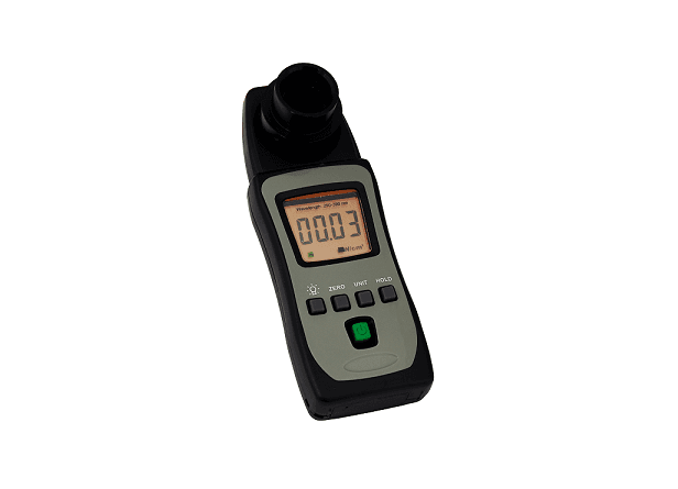
UV Light Intensity Meter / Spot Radiometer

UV Light Intensity Meter / Spot Radiometer is a configurable optical detector or receiver in the Other Components family. The final part number should be released only after the optical, mechanical, electrical and environmental fields below are matched to the intended instrument.

UV Light Intensity Meter / Spot Radiometer

Engineering reference

Specify UV Light Intensity Meter / Spot Radiometer from the interfaces inward

UV Light Intensity Meter / Spot Radiometer is a configurable optical detector or receiver in the Other Components family. The final part number should be released only after the optical, mechanical, electrical and environmental fields below are matched to the intended instrument.

An optical receiver converts incident power into an electrical signal. Material bandgap sets the useful spectral range, while active area, capacitance, gain and front-end bandwidth trade collection tolerance against speed and noise.

The source record contains no configuration table or datasheet. The fields below are therefore procurement requirements to confirm, not claimed values for every option.

Configuration fields to confirm

Spectral response
Specify the operating wavelength range and required responsivity or quantum efficiency within that band.
Signal level
Provide minimum, nominal and maximum optical power so gain and saturation margin can be checked.
Temporal bandwidth
State modulation frequency, rise-time or pulse-width requirements and the intended load impedance.
Noise target
Define acceptable dark current, NEP, input-referred noise or minimum detectable signal at the measurement bandwidth.
Optical interface
Confirm free-space aperture or fiber type, numerical aperture and connector termination.
Electrical interface
Specify bias, transimpedance gain, analog output range, connector, digitizer impedance and power supply.

Qualification sequence

  1. 1Define the measurement objective and the performance limit that UV Light Intensity Meter / Spot Radiometer must satisfy.
  2. 2Freeze wavelength, mechanical, fiber and electrical interfaces before selecting option codes.
  3. 3Check loss, noise, heat, motion or vibration contributions in the complete system budget.
  4. 4Confirm the final drawing, pinout, environmental suffix and acceptance test with the quotation.

Application context

Why this design is used

Application guidance is tied to the configured wavelength, fiber interface and optical-budget fields for this family.

Spectroscopy detection

Detector material and noise must match the spectral band and weak-signal bandwidth, while active area and input optics determine how much dispersed light is collected.

Laser monitoring and control

Bandwidth, saturation power and analog interface determine whether the receiver can close a power-control loop without clipping or adding excess noise.

Technical FAQ

Integration questions for UV Light Intensity Meter / Spot Radiometer

What must be specified before ordering UV Light Intensity Meter / Spot Radiometer?

Confirm spectral response, signal level, temporal bandwidth, noise target, optical interface, and electrical interface. These fields are coupled, so the final part number should be checked against the complete instrument rather than selected from the model name alone.

How should UV Light Intensity Meter / Spot Radiometer be integrated into the system?

An optical receiver converts incident power into an electrical signal. Material bandgap sets the useful spectral range, while active area, capacitance, gain and front-end bandwidth trade collection tolerance against speed and noise. Freeze the optical, mechanical and electrical interfaces before releasing the surrounding assembly.

Which documentation should be approved for UV Light Intensity Meter / Spot Radiometer?

Approve the configuration-specific specification, mechanical drawing, connector or pinout definition, environmental suffix and acceptance-test limits supplied with the quotation. Any field absent from the local record remains a confirmation item, not an assumed capability.

Need this configured?

Share your wavelength, fiber type, connector, power handling and control requirements and we will qualify the matching configuration and part number.
Model selection

Nearby series comparison

Compare UV Light Intensity Meter / Spot Radiometer with the closest available models in the Other Components family. Confirm option-dependent values on the final configuration before ordering.

Selection parameterUV Light Intensity Meter / Spot Radiometer (current)PhotodiodesWavelength-Division Multiplexing (WDM)
Wavelength rangeConfirm for this modelConfirm for this modelConfirm for this model
Optical performanceConfirm for this modelConfirm for this modelConfirm for this model
Fiber typeConfirm for this modelConfirm for this modelConfirm for this model
Connector / controlConfirm for this modelConfirm for this modelConfirm for this model