Spectrometer accessories
Spectrometer Coupling, Slits & Shutters
Interface components connect fibres, camera focal planes and controlled apertures to a configured spectrometer. Choose the mechanical and optical interface as part of the complete measurement path.
Best suited to
Building or adapting an Omni spectrometer experiment.
Selecting a configuration
Supply the exact spectrometer, port, camera focal depth, fibre connector and control requirements. An adapter that fits mechanically still needs the correct optical distance and aperture.
Measurement & configuration
- BFC fibre-coupling adapters.
- Manual or motorised slit configurations.
- Camera flanges and shutter options matched to the port.
Plan the signal path
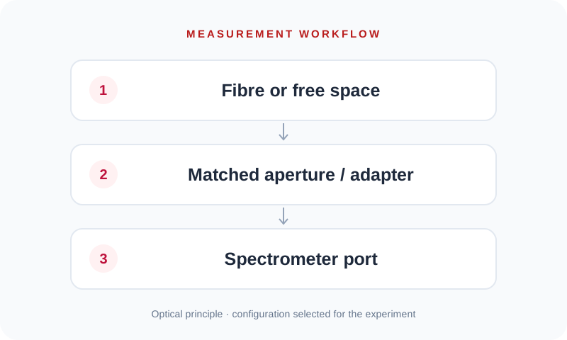
- 1Fibre or free space
- 2Matched aperture / adapter
- 3Spectrometer port
Specifications
| Fibre coupling | BFC family; match connector and optical geometry |
|---|---|
| Slit selection | Match instrument, port, width and height |
| CCD coupling | Flange selected for sensor focal depth and mounting |
| Shutter selection | Match port geometry, timing and control |
| Compatibility | Confirm against the exact spectrometer configuration |
Configuration note: Source pages provide configuration-dependent accessories. No universal camera or fibre compatibility is implied.
Configure BFC / Slits / CCD Flanges / Shutters
Send the wavelength interval, signal level, timing and sample requirements for your experiment.