Optical Switches
Large Core UV-IR High Power Fiber Optical Switch
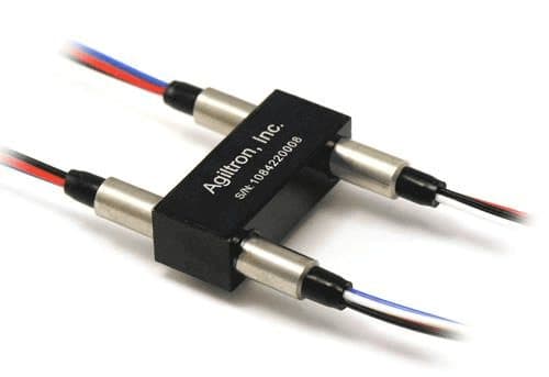
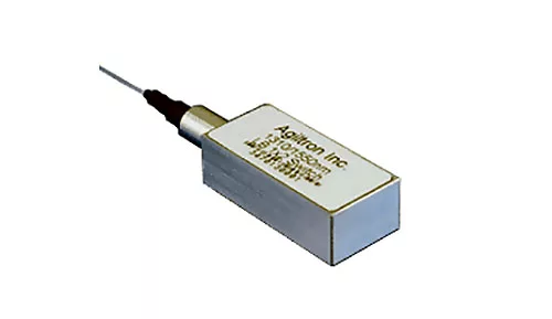
The LFSH Series Fiber Optical Large Core Switch uniquely features high power handling up to 10W for large core fiber up to 1mm in diameter. It directly couples a pair of fibers and is activated via an electrical relay. The advanced design offers unmatched performances of ultra-broadband covering from 300 to 2400nm limited only by fiber intrinsic transmission, low optical loss, little wavelength dependence without coatings, high power handling, as well as low cost. The switch is bidirectional and conveniently controllable by 5V TTL. The latching operation preserves the selected optical path after the drive pulse has been removed, reducing power consumption. The switch has integrated electrical position sensors for verification. The switch is designed to be mounted onto a heat sink to dissipate the unwanted light.
Configuration options
Build & quote
Configure the options below and add your exact build to the enquiry — we confirm the part number and availability.
We confirm the exact part number for your configuration on enquiry.
Power: 5 · Test Wavelength: Any · Package: Standard · Type: Standard · Fiber Core Size: 100 μm (NA0.22) · Fiber Cover: Bare fiber · Fiber Length: 1.0m · Connector: None · Driver: Non
Downloads
Datasheets & documents
System integration
Integration and compatibility
Use these checks to connect Large Core UV-IR High Power Fiber Optical Switch to the surrounding optical, mechanical and control system. Every value shown is taken from this model's own specification record.
- Optical interface and fiber
- Fiber Core Size: 100 μm (NA0.22), 200 μm (NA0.22), 300 μm (NA0.22), 400 μm (NA0.22), 500 μm (NA0.22), 600 μm (NA0.22) · Fiber Cover: Bare fiber, 2 mm Jacket, 900um tube, 3mm Jacket
- Specify connector polish and fiber architecture together. FC/PC, FC/APC and SMA interfaces, and single-mode, multimode and polarization-maintaining fibers, impose different return-loss, mode-field and alignment requirements.
- Wavelength and loss budget
- Test Wavelength: Any, 488, 630, 780, 850, 980, 1060, 1310, 1550, 2000
- Check the Optical Switches passband, insertion loss, return loss and power handling at the actual source wavelength; a nominal telecom-band label is not a substitute for the configured range.
- Control interface
- Driver: Non, USB, RS232, TTL
- Match supply voltage, analog or digital command range, connector pinout and default optical state to the instrument interlock. Confirm the unpowered state explicitly — it decides what happens to the link on a power failure.
Technical FAQ
Integration questions for Large Core UV-IR High Power Fiber Optical Switch
Which fiber and connector does the Large Core UV-IR High Power Fiber Optical Switch use?
Fiber Core Size: 100 μm (NA0.22), 200 μm (NA0.22), 300 μm (NA0.22), 400 μm (NA0.22), 500 μm (NA0.22), 600 μm (NA0.22) · Fiber Cover: Bare fiber, 2 mm Jacket, 900um tube, 3mm Jacket. Specify connector polish and fiber architecture together. FC/PC, FC/APC and SMA interfaces, and single-mode, multimode and polarization-maintaining fibers, impose different return-loss, mode-field and alignment requirements.
How should the Large Core UV-IR High Power Fiber Optical Switch be included in an optical power budget?
Test Wavelength: Any, 488, 630, 780, 850, 980, 1060, 1310, 1550, 2000. Check the Optical Switches passband, insertion loss, return loss and power handling at the actual source wavelength; a nominal telecom-band label is not a substitute for the configured range.
Does the Large Core UV-IR High Power Fiber Optical Switch require a controller?
Driver: Non, USB, RS232, TTL. Match supply voltage, analog or digital command range, connector pinout and default optical state to the instrument interlock. Confirm the unpowered state explicitly — it decides what happens to the link on a power failure.
Need this configured?
Share your wavelength, fiber type, connector, power handling and control requirements and we will qualify the matching configuration and part number.
Model selection
Nearby series comparison
Compare Large Core UV-IR High Power Fiber Optical Switch with the closest available models in the Optical Switches family.
| Selection parameter | Large Core UV-IR High Power Fiber Optical Switch (current) | Large Core UV-IR 1x2 Fiber Optical Switch |
|---|---|---|
| Wavelength range | Any, 488, 630, 780, 850, 980, 1060, 1310, 1550, 2000 | 488nm, 630nm, 780nm, 850nm, 980nm, 1060nm, 1310nm, 1550nm, 2000nm, Special |
| Connector / control | None, FC/PC, SMA | None, FC/PC, SMA |