Optical Modulators
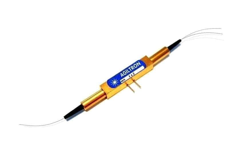
25GHz Lithium Niobate Waveguide Fiber Optical Intensity Modulator
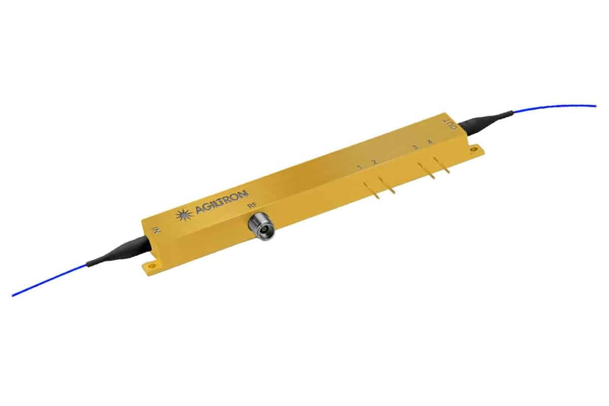
This series of Lithium Niobate (LiNbO3) fiber optic modulators employs a Mach–Zehnder interferometer structure for optical power modulation with low drive voltage, utilizing a traveling push-pull waveguide electrode design. Each Z-cut device integrates a bias control section featuring a built-in micro-heater and an optical power monitor, enabling precise bias adjustment while monitoring output intensity for optimal performance. To compensate for DC drift and maintain the optimal bias point, an optional automatic bias control (ABC) version is available; when selected, the modulator is mounted on a PCB and fully tested prior to delivery. Additionally, a push-pull configuration is available that features two RF driving inputs to achieve zero-chirp operation when driven at a 180° phase difference.
Configuration options
Build & quote
Configure the options below and add your exact build to the enquiry — we confirm the part number and availability.
Part number: LNML-111123551131
Configuration: Amplitude · RF Input: Single · Bias Controller: Non · RF Driver: Non · Wavelength: 1520-1620nm · Frequency: 25GHz · Input Fiber: PM1550 · Output Fiber: PM1550 · Fiber Cover: 0.9mm tube · Fiber Length: 0.5m · Connector: FC/APC · RF Connector: GPPO
Downloads
Datasheets & documents
System integration
Integration and compatibility
Use these checks to connect 25GHz Lithium Niobate Waveguide Fiber Optical Intensity Modulator to the surrounding optical, mechanical and control system. Every value shown is taken from this model's own specification record.
- Optical interface and fiber
- Input Fiber: PM1550 · Output Fiber: PM1550
- Specify connector polish and fiber architecture together. FC/PC, FC/APC and SMA interfaces, and single-mode, multimode and polarization-maintaining fibers, impose different return-loss, mode-field and alignment requirements.
- Wavelength and loss budget
- Wavelength: 1520-1620nm
- Check the Optical Modulators passband, insertion loss, return loss and power handling at the actual source wavelength; a nominal telecom-band label is not a substitute for the configured range.
- Control interface
- Bias Controller: Non, Yes · RF Driver: Non, 4V, 8V
- Match supply voltage, analog or digital command range, connector pinout and default optical state to the instrument interlock. Confirm the unpowered state explicitly — it decides what happens to the link on a power failure.
Technical FAQ
Integration questions for 25GHz Lithium Niobate Waveguide Fiber Optical Intensity Modulator
Which fiber and connector does the 25GHz Lithium Niobate Waveguide Fiber Optical Intensity Modulator use?
Input Fiber: PM1550 · Output Fiber: PM1550. Specify connector polish and fiber architecture together. FC/PC, FC/APC and SMA interfaces, and single-mode, multimode and polarization-maintaining fibers, impose different return-loss, mode-field and alignment requirements.
How should the 25GHz Lithium Niobate Waveguide Fiber Optical Intensity Modulator be included in an optical power budget?
Wavelength: 1520-1620nm. Check the Optical Modulators passband, insertion loss, return loss and power handling at the actual source wavelength; a nominal telecom-band label is not a substitute for the configured range.
Does the 25GHz Lithium Niobate Waveguide Fiber Optical Intensity Modulator require a controller?
Bias Controller: Non, Yes · RF Driver: Non, 4V, 8V. Match supply voltage, analog or digital command range, connector pinout and default optical state to the instrument interlock. Confirm the unpowered state explicitly — it decides what happens to the link on a power failure.
Need this configured?
Share your wavelength, fiber type, connector, power handling and control requirements and we will qualify the matching configuration and part number.
Model selection
Nearby series comparison
Compare 25GHz Lithium Niobate Waveguide Fiber Optical Intensity Modulator with the closest available models in the Optical Modulators family.
| Selection parameter | 25GHz Lithium Niobate Waveguide Fiber Optical Intensity Modulator (current) | 20/40/60GHz Thin Film Lithium Niobate Fiber Optical Phase Modulators – Low Vp | 60/100 GHz Modulator/Fiber Optical Transmitter/Converter – Turnkey |
|---|---|---|---|
| Wavelength range | 1520-1620nm | 1520-1570nm, 1310nm | C-Band, L-Band, 1550 nm, 1551.11 nm, 1562.22 nm, Tunable ITU Laser, 1310 nm |
| Connector / control | FC/APC, FC/UPC, Special | None, FC/PC, FC/APC, Special | FC/APC, FC/UPC, Special |
Related optical modulators
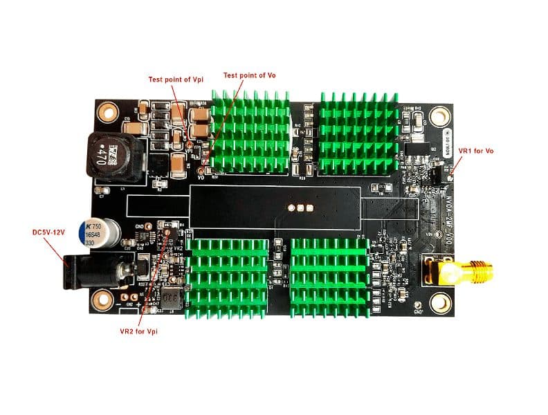 DC-1MHz Driver for NanoSpeed™ Variable Optic Attenuator
- DC-100kHz Driver for NanoSpeed™ Variable Optic Attenuator
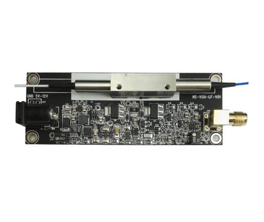 DC-20kHz Driver for NanoSpeed™ Variable Optic Attenuator
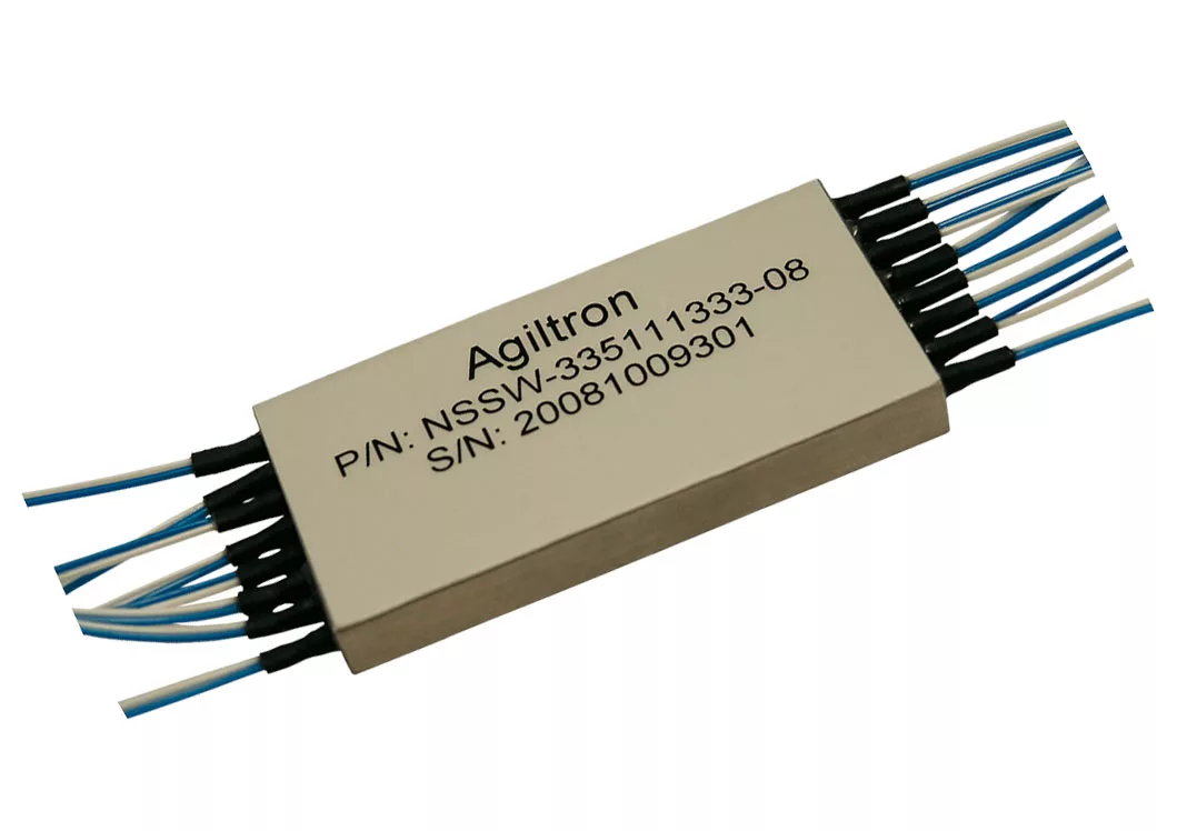 High Speed Variable Fiber Optical Attenuator Array (up to 48 Channels)
 High Speed Broadband Variable Optical Attenuator 950-2400nm, 120nm Coverage
- High Speed Premium Broadband Variable Optical Attenuator 350-2400nm, 120nm Coverage