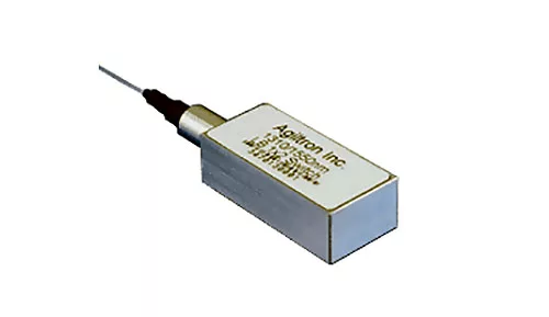
Optical Switches
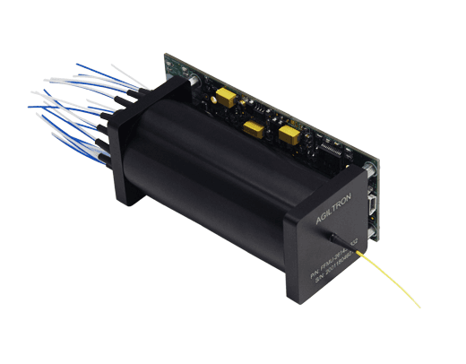
LightBend™ 1xN High Power Fiber Optic Switch
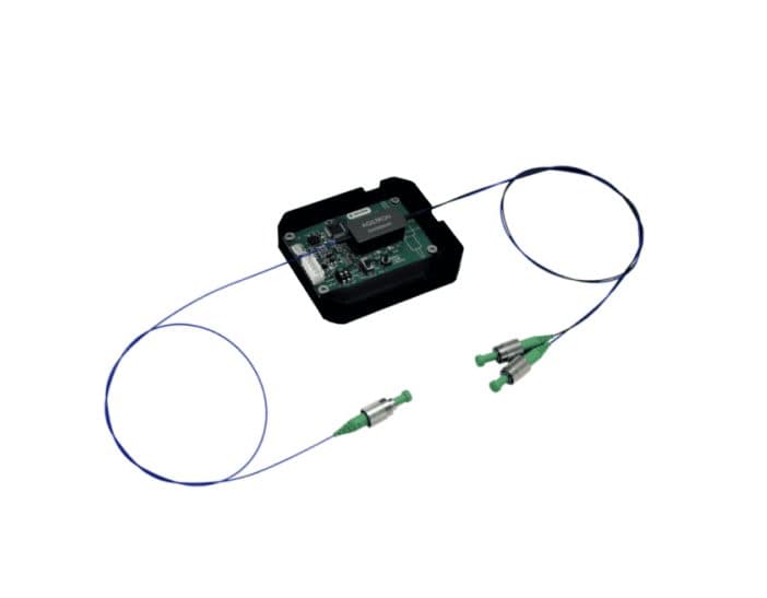
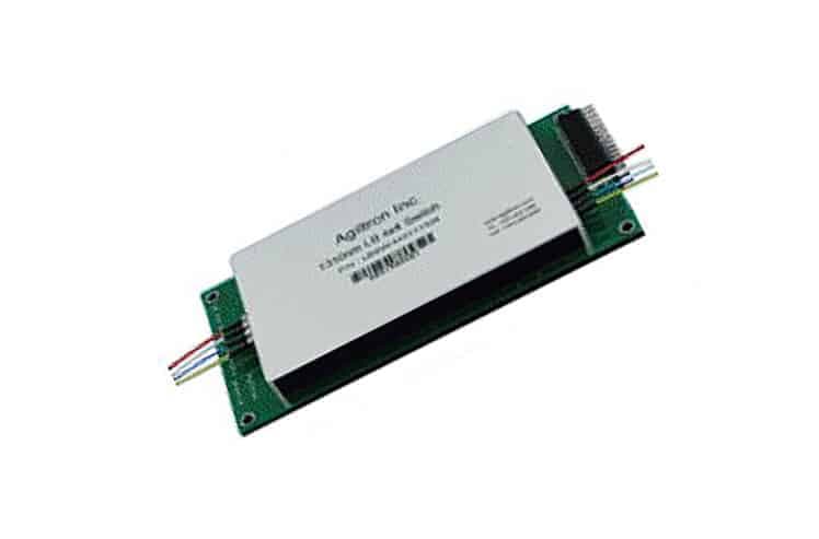
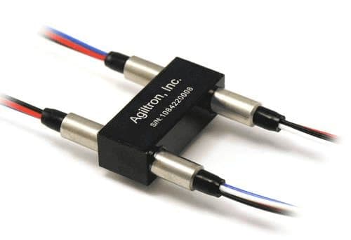
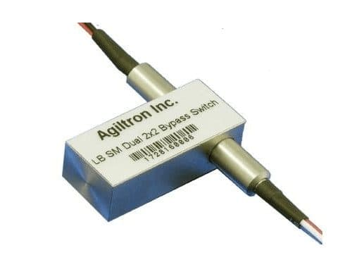
The LBHS Series 1×N Fiber Optic Switch enables high-power optical routing by directing an input signal to a selected output fiber through a precision motor-driven mechanism. The switch achieves fast switching times of less than 5 ms and low insertion loss ~0.3dB. The LBHS is broadband and uncoated, with transmission characteristics equivalent to bare optical fiber. It supports all fiber types and can handle up to 100 W CW optical power when paired with large-core fibers. The switch is bidirectional and offers multiple control interfaces, including TTL, USB, RS232, GPIB, and Ethernet. Note: GPIB and Ethernet interfaces are available only in the 1U rack-mounted configuration.
Configuration options
Build & quote
Configure the options below and add your exact build to the enquiry — we confirm the part number and availability.
We confirm the exact part number for your configuration on enquiry.
Type: 1x4 · Test Wavelength: 1060 · Control: TTL · Optical Power: 0.5 W · Fiber Type: MM 50/125 · Fiber Cover: 0.9mm tube · Fiber Length: 1.0 m · Connector: None · Package: Component
Downloads
Datasheets & documents
System integration
Integration and compatibility
Use these checks to connect LightBend™ 1xN High Power Fiber Optic Switch to the surrounding optical, mechanical and control system. Every value shown is taken from this model's own specification record.
- Optical interface and fiber
- Fiber Type: MM 50/125, MM 62.5/125, 105 μm, 200 μm, 400 μm, SM28, PM1550 · Fiber Cover: 0.9mm tube
- Specify connector polish and fiber architecture together. FC/PC, FC/APC and SMA interfaces, and single-mode, multimode and polarization-maintaining fibers, impose different return-loss, mode-field and alignment requirements.
- Wavelength and loss budget
- Test Wavelength: 1060, 450, 1310, 1410, 1550, 650, 780, 850, 1310/1550, 1260~1620
- Check the Optical Switches passband, insertion loss, return loss and power handling at the actual source wavelength; a nominal telecom-band label is not a substitute for the configured range.
- Control interface
- Control: TTL, RS232, USB, Ethernet, GPIB
- Match supply voltage, analog or digital command range, connector pinout and default optical state to the instrument interlock. Confirm the unpowered state explicitly — it decides what happens to the link on a power failure.
Technical FAQ
Integration questions for LightBend™ 1xN High Power Fiber Optic Switch
Which fiber and connector does the LightBend™ 1xN High Power Fiber Optic Switch use?
Fiber Type: MM 50/125, MM 62.5/125, 105 μm, 200 μm, 400 μm, SM28, PM1550 · Fiber Cover: 0.9mm tube. Specify connector polish and fiber architecture together. FC/PC, FC/APC and SMA interfaces, and single-mode, multimode and polarization-maintaining fibers, impose different return-loss, mode-field and alignment requirements.
How should the LightBend™ 1xN High Power Fiber Optic Switch be included in an optical power budget?
Test Wavelength: 1060, 450, 1310, 1410, 1550, 650, 780, 850, 1310/1550, 1260~1620. Check the Optical Switches passband, insertion loss, return loss and power handling at the actual source wavelength; a nominal telecom-band label is not a substitute for the configured range.
Does the LightBend™ 1xN High Power Fiber Optic Switch require a controller?
Control: TTL, RS232, USB, Ethernet, GPIB. Match supply voltage, analog or digital command range, connector pinout and default optical state to the instrument interlock. Confirm the unpowered state explicitly — it decides what happens to the link on a power failure.
Need this configured?
Share your wavelength, fiber type, connector, power handling and control requirements and we will qualify the matching configuration and part number.