Laser beam conditioning
Dichroic Filters: Substrate, coating band and surface figure set the transmitted or reflected wavefront, and the damage threshold sets the power the optic can carry.
Optics, filters & coatings
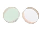
Dichroic filters are designed for use at a 45° angle of incidence and separate light by transmitting one band and reflecting another. Mainly used in fluorescence microscopy and for filtering spectral components. Stocked models cover 532 nm and 785 nm.
| Wavelength | Model | Filter type | Sizes (mm) | Stock status |
|---|---|---|---|---|
| 532 nm | 532-LDAB-50AB-S | Dichroic filter | 25.4×25.4×2, 12.7×12.7×2 | In stock |
| 785 nm | 785-LDAB-50AB-S | Laser dichroic filter | D25.4×2, 25.4×25.4×2, 12.7×12.7×2 | In stock |
Application context
Application fit depends on the ordered configuration; catalog values are separated from fields that still require confirmation.
Dichroic Filters: Substrate, coating band and surface figure set the transmitted or reflected wavefront, and the damage threshold sets the power the optic can carry.
Dichroic Filters: Edge steepness, blocking depth and passband transmission at the working angle decide how well the excitation is separated from the signal.
Engineering reference
Dichroic Filters is a configurable free-space optical component in the Optics, filters and coatings family. The final part number should be released only after the optical, mechanical, electrical and environmental fields below are matched to the intended instrument.
A free-space optic is specified by the wavelength band and angle of incidence its coating is designed for, the clear aperture the beam actually uses, and the substrate, surface quality and damage threshold the application demands. Catalogue figures are quoted at a reference wavelength and angle; performance shifts away from them.
Selection guidance describes the engineering fields that must be checked. It does not assign an option-dependent value that is absent from the catalog record.
Technical FAQ
Confirm wavelength and coating band, angle of incidence and polarization, size and clear aperture, substrate and surface quality, power handling, and mounting and environment. These fields are coupled, so the final part number should be checked against the complete instrument rather than selected from the model name alone.
A free-space optic is specified by the wavelength band and angle of incidence its coating is designed for, the clear aperture the beam actually uses, and the substrate, surface quality and damage threshold the application demands. Catalogue figures are quoted at a reference wavelength and angle; performance shifts away from them. Freeze the optical, mechanical and electrical interfaces before releasing the surrounding assembly.
Approve the configuration-specific specification, mechanical drawing, connector or pinout definition, environmental suffix and acceptance-test limits supplied with the quotation. Any field absent from the local record remains a confirmation item, not an assumed capability.