Sub-2000
100 × 100 mm square- Single-field fit (XY)
- Fits in one field
- Block size (XYZ)
- Within the published limit
- Minimum writing timeAt 2,000 points/s
- 60 s
Maximum crystal dimensions · 150 × 250 × 100 mm
A subsurface engraver builds an image from points written at different depths inside a transparent block. The artwork’s outline determines whether it fits in one field. Its point count determines the shortest possible writing time.
Compare my design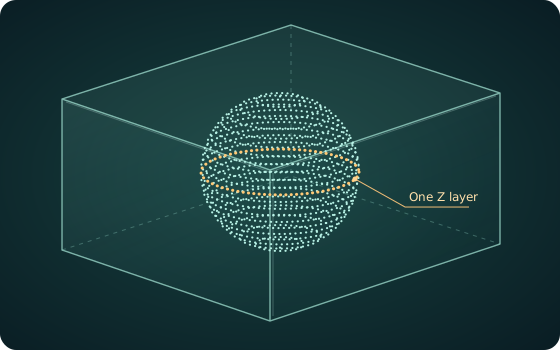
Enter the block as mounted and the full extent of your artwork. X and Y are the top view. Z is the span through the glass. Use the point count from the finished engraving file.
The centred artwork clears all six block faces.
Maximum crystal dimensions · 150 × 250 × 100 mm
Maximum processing envelope · 320 × 250 × 100 mm
Both top views use the same scale and assume centred, axis-aligned artwork. Times use point count ÷ maximum engraving rate, even when a fit check fails. Loading, focusing, repositioning and inspection add to the cycle.
Request a sample review with these dimensionsMeasure the footprint of all the points viewed from above. A letter on the front of a 3D design and a feature at the back may set opposite limits. Use rectangular bounds for text, logos and irregular point clouds. Choose the ellipse option if the whole design lies inside that oval.
The Sub-2000 has a square field. On the Sub-6000, the available width narrows towards the ends of the elliptical field. For example, a centred 140 × 100 mm rectangle puts its corners outside the Sub-6000 field. A 140 × 100 mm ellipse fits. For sparse artwork, inspect the outermost marked points if the bounding rectangle fails.
For a centred rectangle of width W and length L in millimetres, all four corners fit when (W / 160)² + (L / 130)² ≤ 1. A 140 × 100 mm rectangle gives approximately 1.36. For an aligned elliptical outline, its two full axis lengths must each fit within the corresponding field axis.
For the block-size check, the Sub-2000 specifies maximum crystal dimensions and the Sub-6000 specifies a processing envelope. Both extend to 100 mm in Z. Confirm the reachable writing depth, clearance to each face and fixture space for the chosen material. If a design crosses a field boundary, ask for a repositioning and registration trial to see how adjoining features meet.
| Specification | Sub-2000 | Sub-6000 |
|---|---|---|
| Single field (XY) | 100 × 100 mm | 160 × 130 mm ellipse |
| Maximum block / processing envelope | 150 × 250 × 100 mm | 320 × 250 × 100 mm |
| Maximum engraving rate | 2,000 points/s | 4,000 points/s |
| Engraved point size | 100 µm | 40–80 µm |
Choose where the points belong. For a hollow object, points on the surface can describe its form. Filling its volume adds interior points and writing time. Export the final count after setting the spacing and removing unused geometry. A CAD model’s vertex count can change when it is converted into an engraving file.
Check detail in the intended glass. Point size describes one engraved mark. Point spacing describes the distance between marks. The Sub-6000 lists 40–80 µm points and 70–120 µm spacing. For small lettering or fine contours, inspect a representative piece at the intended depth and under the intended display lighting.
Time a complete part. At the published maximum rates, 120,000 points take at least 60 seconds on the Sub-2000 and 30 seconds on the Sub-6000. Doubling the number of written points doubles those minima. For a production estimate, time a sample from loading to unloading with the actual point file and fixture.
For a sample review, include the glass grade, block dimensions, artwork extent, point count and target cycle time. Use your planner settings in the enquiry.
For marks on the surface of a part, see the laser marking and engraving guide (opens in a new tab).