Photodetectors – Components, Fiber-Coupled, Amplifier-Integrated, DC–100 GHz
Optical WDM Channel Monitoring System
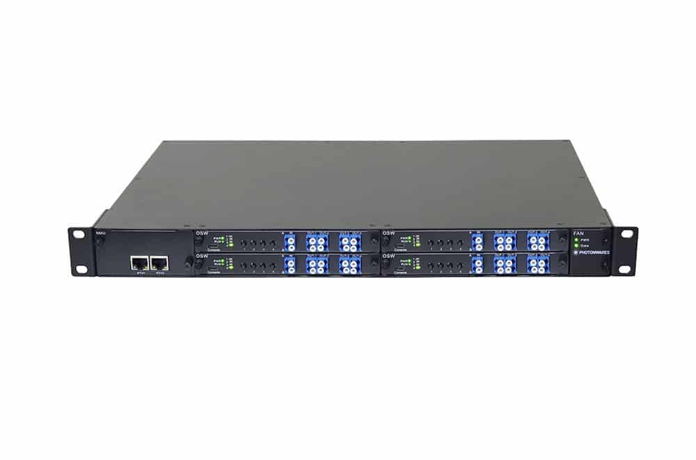
The FCMS Series Fiber Optical Channel Monitor System is a versatile turn-key solution for cost-effective monitoring of any channel in a multi-channel fiber-optic network, supporting up to 260 channels across multiple fibers or multiple wavelengths within a single fiber. Each FCMS unit integrates precision photodetectors and low-noise amplifiers to provide accurate optical-power measurements, digitally displayed through an intuitive GUI. The system supports either instantaneous readings (<1 ns) or fast full-scan mode (20 ms) across all channels. Fibers can be connected directly into the FCMS or routed through for uninterrupted transmission, with only 3% tapped for monitoring. Standard interfaces include USB, RS-232, Ethernet and a complete command set is provided to simplify customer software development.
Configuration options
Build & quote
Configure the options below and add your exact build to the enquiry — we confirm the part number and availability.
We confirm the exact part number for your configuration on enquiry.
Channels: 8 · Wavelength: 1230-1630 · Switching Time: 20ms · Tap Ratio: Direct · Fiber Type: SMF-28 · Connector: FC/PC · Interface: USB
System integration
Integration and compatibility
Use these checks to connect Optical WDM Channel Monitoring System to the surrounding optical, mechanical and control system. Every value shown is taken from this model's own specification record.
- Optical interface and fiber
- Fiber Type: SMF-28, MM 50/125, MM 62.5/125 · Connector: FC/PC, FC/APC, SC/PC, SC/APC, ST/PC, LC/PC, Duplex LC/PC, Quad LC/PC, LC/UPC, MPO, Special
- Specify connector polish and fiber architecture together. FC/PC, FC/APC and SMA interfaces, and single-mode, multimode and polarization-maintaining fibers, impose different return-loss, mode-field and alignment requirements.
- Wavelength and loss budget
- Wavelength: 1230-1630, CWDM, DWDM
- Check the Photodetectors – Components, Fiber-Coupled, Amplifier-Integrated, DC–100 GHz passband, insertion loss, return loss and power handling at the actual source wavelength; a nominal telecom-band label is not a substitute for the configured range.
- Control interface
- Switching Time: 20ms, 1ns
- Match supply voltage, analog or digital command range, connector pinout and default optical state to the instrument interlock. Confirm the unpowered state explicitly — it decides what happens to the link on a power failure.
Technical FAQ
Integration questions for Optical WDM Channel Monitoring System
Which fiber and connector does the Optical WDM Channel Monitoring System use?
Fiber Type: SMF-28, MM 50/125, MM 62.5/125 · Connector: FC/PC, FC/APC, SC/PC, SC/APC, ST/PC, LC/PC, Duplex LC/PC, Quad LC/PC, LC/UPC, MPO, Special. Specify connector polish and fiber architecture together. FC/PC, FC/APC and SMA interfaces, and single-mode, multimode and polarization-maintaining fibers, impose different return-loss, mode-field and alignment requirements.
How should the Optical WDM Channel Monitoring System be included in an optical power budget?
Wavelength: 1230-1630, CWDM, DWDM. Check the Photodetectors – Components, Fiber-Coupled, Amplifier-Integrated, DC–100 GHz passband, insertion loss, return loss and power handling at the actual source wavelength; a nominal telecom-band label is not a substitute for the configured range.
Does the Optical WDM Channel Monitoring System require a controller?
Switching Time: 20ms, 1ns. Match supply voltage, analog or digital command range, connector pinout and default optical state to the instrument interlock. Confirm the unpowered state explicitly — it decides what happens to the link on a power failure.
Need this configured?
Share your wavelength, fiber type, connector, power handling and control requirements and we will qualify the matching configuration and part number.