RF Over Fiber Link System 10MHz-40GHz Multichannel Analog/Digital Turn-Key
RF Over Fiber Link System – 3GHz Analog/Digital 18 Channels
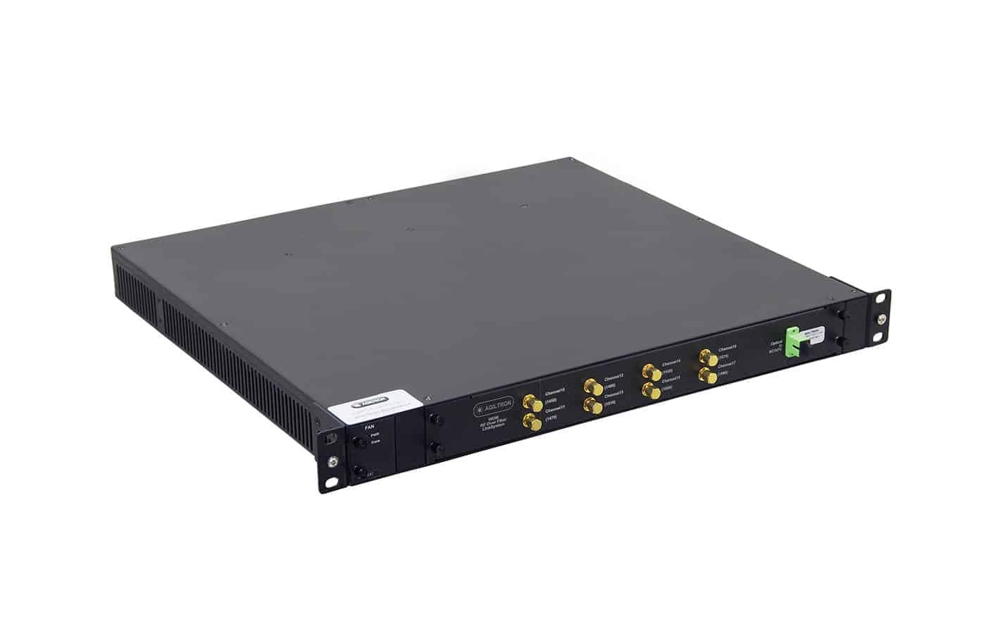
The RF over Fiber (RFOF) Link Series is designed for high-fidelity transmission of analog and digital RF signals up to 3 GHz over distances of up to 1 km. The system converts electrical RF signals into optical signals using a directly modulated laser at the transmitter. At the receiver, a high-linearity photodiode and low-noise amplifier convert the optical signal back into an RF signal, providing a transparent and high-performance data transmission channel. This series supports all 18 CWDM wavelengths specified by the ITU, ranging from 1271 nm to 1611 nm. When paired with a CWDM multiplexer, multiple independent channels can be transmitted over a single shared fiber link. Additionally, an optional bidirectional RF communication feature enables two-way transmission over a single fiber strand using adaptors.
Configuration options
Build & quote
Configure the options below and add your exact build to the enquiry — we confirm the part number and availability.
Part number: CRFO-0101101021
# of Tx: 1 · # of Rx: 1 · # of Fiber: 1 · Link Length: < 1km · CWDM: None · Fiber Connector: FC/APC · RF Connector: SMA
System integration
Integration and compatibility
Use these checks to connect RF Over Fiber Link System – 3GHz Analog/Digital 18 Channels to the surrounding optical, mechanical and control system. Every value shown is taken from this model's own specification record.
- Optical interface and fiber
- # of Fiber: 1, 2, 3, 4, 5 · Fiber Connector: FC/APC, Special
- Specify connector polish and fiber architecture together. FC/PC, FC/APC and SMA interfaces, and single-mode, multimode and polarization-maintaining fibers, impose different return-loss, mode-field and alignment requirements.
Technical FAQ
Integration questions for RF Over Fiber Link System – 3GHz Analog/Digital 18 Channels
Which fiber and connector does the RF Over Fiber Link System – 3GHz Analog/Digital 18 Channels use?
# of Fiber: 1, 2, 3, 4, 5 · Fiber Connector: FC/APC, Special. Specify connector polish and fiber architecture together. FC/PC, FC/APC and SMA interfaces, and single-mode, multimode and polarization-maintaining fibers, impose different return-loss, mode-field and alignment requirements.
Need this configured?
Share your wavelength, fiber type, connector, power handling and control requirements and we will qualify the matching configuration and part number.