SLE-IV-B
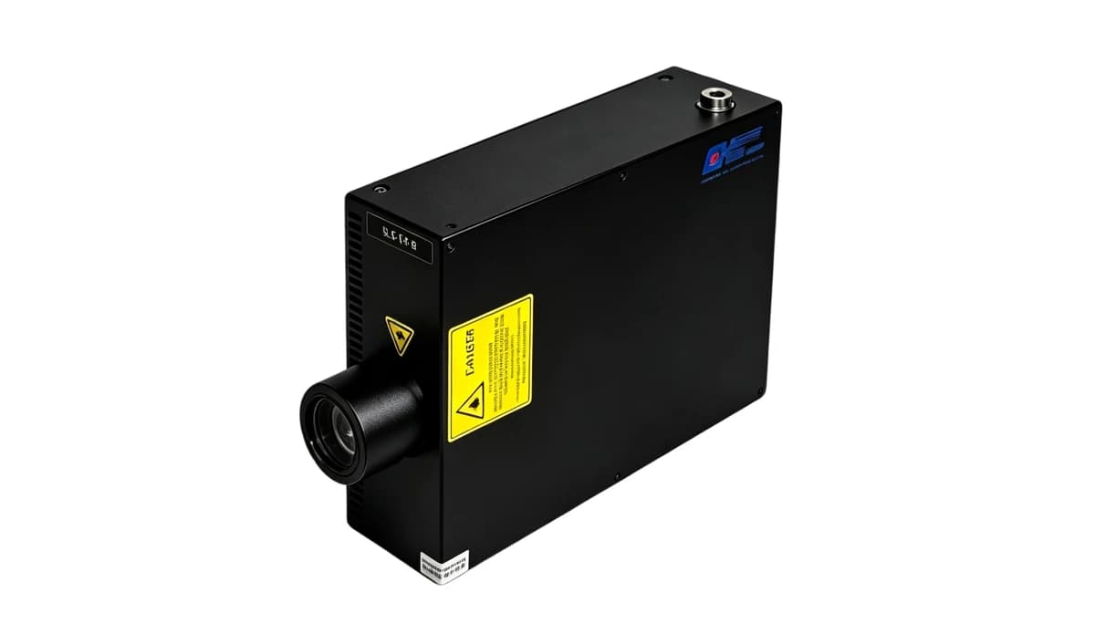
SLE-IV-B multi-channel light engine
SLE-IV-B combines 4 optical channels with LED peaks at 385 nm/460 nm/555 nm/625 nm. Compare channel powers, control, optical delivery and cooling as one illumination system.
Compare the details
Technical specifications
Compare the listed configurations and match the specifications to your setup.
16 specification rows.
Model specifications
16 entries| Parameter | Specification |
|---|---|
| Model | SLE-IV-B |
| Channel count | 4 |
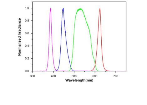
| Published spectral range | 375-640 nm |
| LED peak wavelengths | 385 nm/460 nm/555 nm/625 nm |
| Lifetime | 20000 h |
| Output power | 950 mW@385 nm; 3200 mW@460 nm; 1600 mW@555 nm; 780 mW@625 nm; (Output power per source channel is dependent on filter bandpass) |
| Intensity control | Four independent controls, 0-100% dimming, accuracy of 1% |
| Rise / fall time (10-90%) | Rising/ Descending Edge (10%-90%) <50 microseconds |
| Operating Mode | Continuous Output, Default TTL Modulation (Analog Modulation Optional) |
| Computer control | Support RS232 host computer control |
| Control Options | SMA - External trigger TTL signal (external trigger analog modulation optional); Serial Interface (RS232) - Light Output ON/OFF and brightness adjusting; Manual control box (optional) - Light Output ON/OFF and brightness adjusting |
| Operating Temperature | 10-35°C |
| Power input | DC12 V |
| Cooling | Air Cooled |
| Source warranty term | 1 Year |
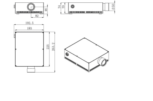
| Housing dimensions (reference) | 263.2 mm×192.5 mm×74 mm (Reference) |
Scroll within the table to view every row.
Spectrum & mechanical references
Relative emission spectrum
Mechanical drawing
Complete the illumination path
01
Define the spectrum
Start with the absorption, excitation or inspection band. Use the model’s wavelength bin or LED peaks and its FWHM; a family range describes separate configurations.
02
Choose the optical path
Use a fiber-coupled module for remote delivery, a light engine for a controlled source assembly, or a PCB emitter when your instrument provides the driver, optics and cooling.
03
Match power to the interface
For fiber output, choose core diameter and numerical aperture before reading the power column. For engines, check the lightguide or bundle and filter conditions. PCB emitter power is not a fiber-delivered rating.
04
Specify control and cooling
Match current, voltage compliance and heat removal to the exact device. Select TTL, analog or RS232 only where specified. Include mounting, connector and synchronization requirements in your enquiry.