LED-670-P1
LED-670-P1 PCB-mounted LED
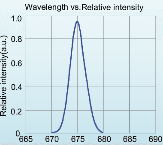
- Peak Wavelength: Minimum: 670 nm; typical: Not specified; maximum: 680 nm
- LED Output Power: Minimum: 487.8 mW; typical: 582 mW; maximum: Not specified
- Forward Voltage: Minimum: 2 V; typical: 2.4 V; maximum: Not specified
- Bandwidth (FWHM): Minimum: Not specified; typical: 22 nm; maximum: Not specified
- Typical Viewing Angle: Minimum: Not specified; typical: 120 deg; maximum: Not specified
- Maximum Current: 700 mA
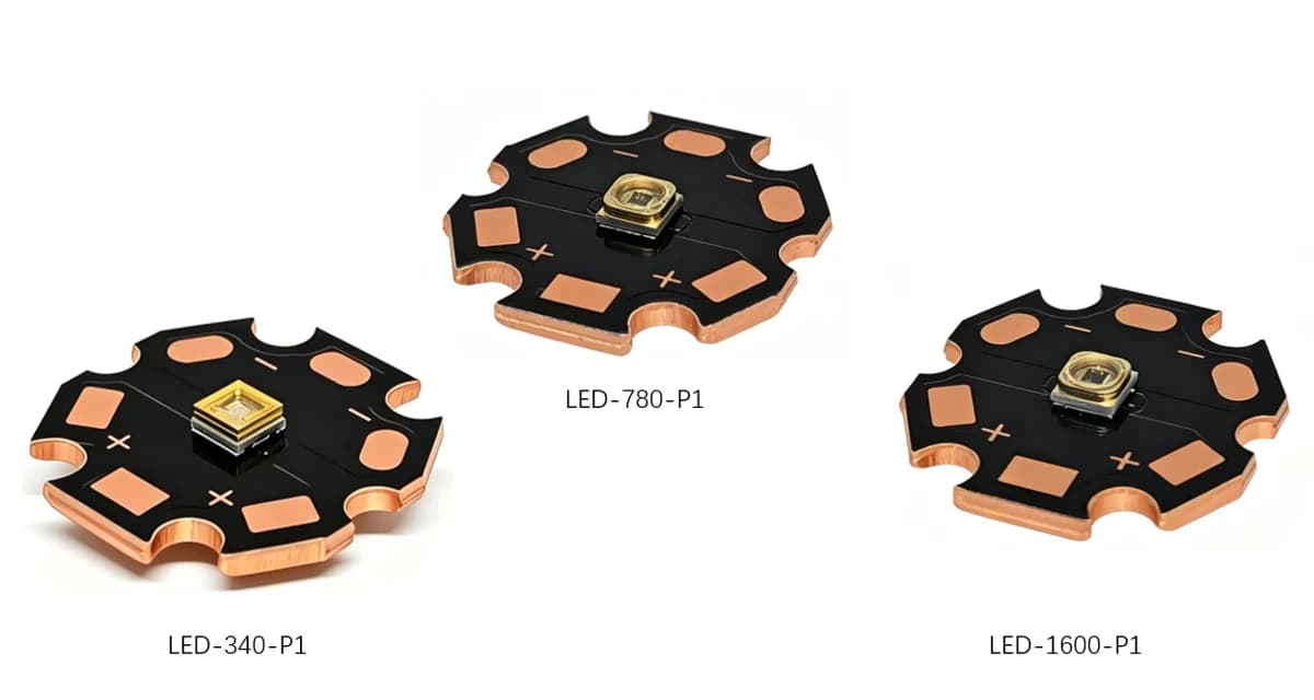
Compare the details
Technical specifications
Compare the listed configurations and match the specifications to your setup.
Jump to a specification table (2)
10 specification rows.
Optical and electrical ratings
5 entriesScroll horizontally to compare all columns
| Parameter | Minimum | Typical | Maximum |
|---|---|---|---|
| Peak Wavelength | 670 nm | Not specified | 680 nm |
| LED Output Power | 487.8 mW | 582 mW | Not specified |
| Forward Voltage | 2 V | 2.4 V | Not specified |
| Bandwidth (FWHM) | Not specified | 22 nm | Not specified |
| Typical Viewing Angle | Not specified | 120 deg | Not specified |
Not specified means the source gives no value. Maximum current is a limit, not an instruction to operate every device at that current.
Operating limits and carrier
5 entries| Parameter | Rating |
|---|---|
| Maximum Current | 700 mA |
| Operating Temperature | -40 to +85°C |
| Storage Temperature | -40 to +100°C |
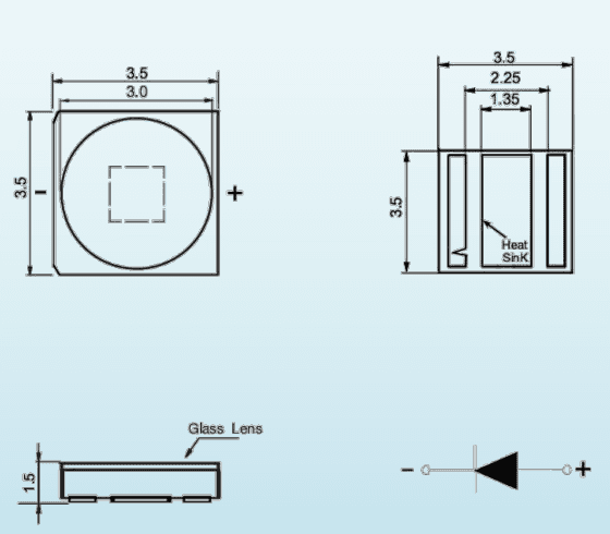
| Carrier | 20 mm hexagonal copper-core PCB |
| Thermal management | Heat sink required |
Construction details
- Emitter carrier: 20 mm hexagonal copper-core PCB.
Spectrum & mechanical references
Emitter package drawing
Relative emission spectrum
Complete the illumination path
01
Define the spectrum
Start with the absorption, excitation or inspection band. Use the model’s wavelength bin or LED peaks and its FWHM; a family range describes separate configurations.
02
Choose the optical path
Use a fiber-coupled module for remote delivery, a light engine for a controlled source assembly, or a PCB emitter when your instrument provides the driver, optics and cooling.
03
Match power to the interface
For fiber output, choose core diameter and numerical aperture before reading the power column. For engines, check the lightguide or bundle and filter conditions. PCB emitter power is not a fiber-delivered rating.
04
Specify control and cooling
Match current, voltage compliance and heat removal to the exact device. Select TTL, analog or RS232 only where specified. Include mounting, connector and synchronization requirements in your enquiry.